This Work Shop Web pages are here for people that have little skills, who are willing to follow instructions and seriously want to build and are looking for more ideas in order to enhance their own abilities in the field of electronics or general building skills for creating power towards self preservation. I will not be answering any emails for obvious reasons. I urge you to exercise utmost precaution in copying the work on these pages. As you work on HV stand on a rubber mat, keep one hand in the pocket and observe all the safety rules taught in cyber space. You are following my building instructions at your own risk while you are in agreement in taking full responsibility for your own work done and all outcome thereof.
Because of the twisting slimy slithering liars this chapter is now closed too.
From: Rick
To: erwin@columbiacable.net
Sent: Wednesday, October 19, 2005 10:13 AM<>
Subject: From John
He is free to experiment like everybody else with the device. You just can not turn into a business for profit. There are a lot of people with Internet pages on this device. He may post what he wants too.
John Bedini.
A text on part of John Bedini's inventions --->
http://www.rexresearch.com/bedini/bedini.htm#bedkeelynet
What does SSG mean: Simplified School Girl-----> http://groups.yahoo.com/group/Bedini_Monopole/
John Bedini placed some important posts at the beginning stages of the groups to get them going, so did Rick Friedrich all through, along with some friends well versed in the technology. I hope I didn't bungle up too much of what they taught, with my own ideas on my pages. I spent many hours making notes from studying all the posts. So all I am doing here really, is also lending a helping hand for the ones that want to learn this technology. Teaching people to build SG's is really John and Rick’s basic Idea in the first place.
You might wonder about the purpose of just charging batteries. To your pondering I am asking you, do you have enough knowledge and know how to build an efficient perhaps self running energizer off of its own capacitor or fed by batteries which charge themselves resulting of your setup.... create a machine that has enough power output for self preservation.....? Well then, get going.... you have to start some where!!!One thing is for sure; if you tackle the Bedini circuit, you are in for some pleasant surprises!
I would like to get you on the self running thinking track right off the bat, which does not happen automatically, because one tends to forget
The out of phase principle (but doesn't have to be) is roughly explained in picture form of my schematics page, Image 16a, Motor sketch out of my shop note book.
For the generating coils I'd try 1000 ft or more of # 20 to 23AWG single strand, or more strands see Image 12 below, rectified charging a capacitor and timed commutator dump. Would be interesting to note the difference between a standard charging coil versus a HV coil to charge batteries with.
John Koorn also a lively Bedini tech. experimenter has some interesting news in his lab notes regarding the back-popping experiment from the generator coil.
http://tech.groups.yahoo.com/group/bedini_monopole2/message/3387
If you are interested in how I switch to primary charge of the self running monopole, then go to schem. page index oo Monopole magneto 11a.
Also see out of phase: http://www.sayedsaad.com/fundmental/5_Sine%20Wave%20In%20Phase.htm
To prevent you from confusion, Rick's SG was designed with the window motor mode in mind, meaning a change of magnet polarity at every 180º, and horizontal coil of 800 turns wrapped around the whole machine which is the reason Rick calling it a hybrid SG. Start small and stick to the conventional SG design and keep John Bedini's 10 and 12 coiler in mind!!!
Peswiki:
http://peswiki.com/index.php/Directory:Bedini_SG:Self-Runner
http://peswiki.com/index.php/Directory:Bedini_SG:Self-runner:Details
Most of Tom Bearden's writings have only value for people who are interested in theory and can understand it, but has little meaning for practical applicators, which is just my humble opinion. John Bedini is an engineer, I'm not!
Rick is forgetting that John Bedini was pushed against the wall, hence his explanations are limited. The 1984 book is not easy to replicate without any help, which is the reason people haven't tackled it, same with ‘Increased Volts’ by Rick. It is one thing to demonstrate a working principle, but another thing to produce a practical working machine. I do not like the words "spoon feeding" since there are many people who would give things a whirl while getting some clear explanations and pointers along with it, which is what helping your neighbor is all about. Just because I have been given a certain ability to accomplish a certain thing toes not mean my neighbor is gifted with the same, which is the reason we ought to help each other out.
__________________________________________________________
Tools needed, see General Parts
Before you'll start building, study all drawings carefully, make notes while you cover all text, thus you'll get most of your questions answered. Re-read my text every once in a while. I keep adding and changing things!!! If you read my whole text you will see my steady progress since I started this website, hence you will find paradoxes since I seldom erase remarks I had made even if found that I was wrong. Through someone else's mistakes one can learn not to make the same. Besides thinking about the paradoxes, it will motivate your thinking-cap for some better choices!
Start with the basic small machine. Choose the board size (stator plate) with upgrading in mind like adding coils. You will be able to use it for the small batteries besides you are learning the most important part of the technology, which is switching the radiant energy. I find myself charging Ni-Cad."D" sells most often for my flash lights and lanterns. Radio Shack makes the best on the market. The NI-Med-Hydr. I am trying out right now.
You can always join Rick's group and study the many hundred posts if you don't mind wasting your time getting to know the illuminati pack's side trails, because it will take you a while to keep apart the good from the bad, the one who is really trying to help and the one trying to mislead!
1. Casting a Plastic "Yogurt" Rotor
For size 1/2 x 1 x 2" 13x 25x/50mm ceramic
ferrite magnets,
they
should be 70mm long, but are not available (except if you want to reed
the two last lines of the magnet paragraph 3).
2. Rotor mold:
Glue in the magnets with E-Z "Super Glue" (do not count on any glue for a permanent bond!!!)
Placing the safety strap on the low profile rotor, make certain the strapping is placed above the center of the magnets for clamping them onto the solid plastic!!! Drill and tap for two oval tapered sst machine screw and sink them into the epoxy with a file or rotary power tool in order to get the screw heads flush with the circumference of the rotor, then balance the rotor on two bearings.
Shortcut: Depending on your accuracy with your eyes and hands, you might be able to cast a rotor freehanded and balance it, as described, without vibration as an end result. Saw or file out the pattern of the two perforated (drill holes) 1/8th plywood or ABS discs with equal spaces for the mags and a hole in the center to take the shaft, drill the flow holes for the resin equally around the disks, fasten the disks onto a mandrel or bolt with nut and true them up in the drill-press-chuck by lowering the spindle with rotating mandrell onto a bolted down cutter. You might setup your dove tail magnets in a radial fashion on a straight/level platform with a hole in the center and glue the disks onto the mags 1/2 inch from the ends using spacers on the disks in relation to the level surface, place the glued up assembly with the shaft in the drill press chuck and check it out. Cut and wax up two thin peaces of plastic for the side and the lower end and tape it all together and pour the mould. Besides this exercise being a good practice for an accuracy discipline I wish you good luck, but do not recommend this procedure.
2a. Commutator mold:
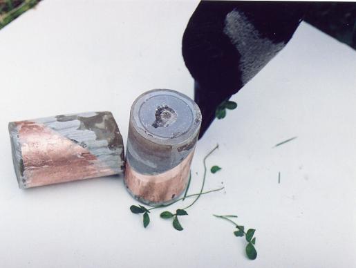
1 - 1/4" copper coupling was cut on a 45º angle making sure to keep the copper nice and round, then wrapped with card board and lots of masking tape for the mold, 1/2" longer then the copper remembering space for set screws, then filled with resin. As you will see in image 2a there are some imperfections which are just gone over with resin and putty knife or brush. When chucked in the lathe true up along the copper surface with dial indicator once you think all low spots are taken care of. File the resin where the jaws are grabbing it until the work peace runs true, then use the center drill for life center application.
You need to use two 1/4 NC set screws in the epoxy from both sides, that way you don't have to tighten them too much. Don't use more than 10% talcum powder or none at all in the resin in this case depending on size, just cool it in cold water while it is hardening if you can't touch it anymore. If you strip the threads, drill it up to 1/2NC, pour the bore with straight resin again and re-cut the 1/4 NC thread, it's easy, and it cuts like cheese :)
.
Image 2a
3. Magnets:
In JB's drawing “Simple Hook Up”, the ferrite magnets are glued on top of the roller skate wheel and in the lower drawing the magnets are machined, hand worked, glued or cast inside the outer circle. (Use ferrite magnets only).
Very important:
1. Do not use round magnets for serious testing and work, the Magnets must be the width of the coil, as JB's lower drawing is showing, unless you build the motor just for fun and play.
2. The magnets must be placed at least 1 1/2 times their width apart from each other around the circumference of the wheel. 13 x 25 x 50mm is a good size for starters, 70mm would be even better if you can find them since your coil DIA is around 70mm. Don't hesitate to start with 50mm magnets, if you later on decide for bigger coils you can always glue a 4" 10mm magnet on top of the 50mm which works out quite well, if you manage to line them up properly, use a flat surface and blocks, which is not easy to do; if you don't mind the wind created by the tall magnets, that is. A 5" rotor is not to bad for wind if you rap a bit of plastic around it. Anything bigger, you'd be better off going with a solid volume rotor and consider the benefit of the kinetic energy created at high RPM's for a self runner, once you learn how to setup or switch the energy accordingly!
3. Use a compass and check the magnets for north, be carefully not to go closer than 12" near the magnet, in order not to damage the compass. The face of the magnet is south which the north needle of the compass is pointing to, only if the N-needle is deflecting off the magnet is it a north face, mark the north face with an felt-pen before you glue them onto the wheel with the north mark facing out. If you are still not sure , then take a map, or orient yourself of your North position knowing that the sun rises at the east and sets in the west, stretch out your right arm towards east and the left towards west, now you are looking north. Place a string around your magnet with the poles horizontally oriented and hold the string in the air, you have to play a little with it until the magnet no longer moves, then mark it north, repeat it three four times. Remember that like poles repel each other, hence the north needle of a compass has to be pointing to the opposite pole of a magnet held in front of it. The motor will not work with top performance if you mount the magnets south poles out ward.
Once you need to buy more and bigger magnets, a cheaper way is to acquire 25x100x150mm (1x4x6”) slabs for around $28.00 CAD. at
1x1x4 grade 8 ferrite mags are available at: http://www.northwestmagnet.com/permanent-magnets.html
Use your rain gear, running a Masonry diamond disc saw, water tray is a must, otherwise the mags. get hot with the result of cracking and losing magnetism, cut 6 -- 1x1x4” and 4 – 1x1x6 bars for your bigger SG rotors. Make sure you stop short by turning the mags around to finish the cuts and hold them down firm, because they want to flip around at the end of the cut. If you are not quite with it, you'll wake up real quick on this job!!! Cut them as precise to size and weight as you possibly can. Have a scale handy since you have to finish trimming them anyhow. Dove-tail shape magnets is the answer if you are not using copper bands around the rotor circumference. Make yourself a jig for the masonry diamond disc saw and grind between 10 and 15 degrees ceramic material off of each side.There is one way to get your 3" 75mm mags, which is by cutting four strips, length wise of the 6" slab and cutting them in half. Again keep in mind that you will not be able to cut all the magnets exactly to same size which will cause an imbalance in the rotor which you must correct. If you weigh them carefully and keep cutting them to the right weight it helps a lot.
5. Balancing:
Most of the vibration caused is in the imbalance of the rotor, seldom the shaft. Placed the rotor/axle on two straight edges or clamp the base-board perpendicular in a vice placing the rotor (axis) in a horizontal position and balance it properly, meaning wherever it stops, stick some nails on the magnet on the opposite side, mark the spot and weigh the nails and replace with copper or peaces of copper wire, epoxy glue, with a strip of mask. tape to hold it there 'till hardened. Proceed with this operation until the rotor always stops on a different location.
The spinner of my SSG4a is a "yogurt" rotor with a 4 mm shaft, I am very pleased with it, considering it being plastic, to say the least. Because of the 2" leverage, I had to use a life center off a bearing to keep it steady, (It was vibrating on the top of the shaft just like a top does) using the acrylic strip, but build it heavier then mine; Much simpler than sliding the bearing over the shaft.
For a fast jobby and fun
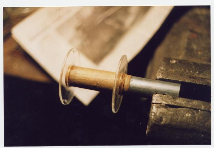
We need 3/16" - 5mm acrylic sheet (Plexy Glass), Lexan is stronger not as brittle and nicer to work with but more expensive or a door skin usually 1/8 plywood, a couple of bar clamps (with wooden handles) the first one, top left in the following link if you can not see image 2, then copy: http://www.bosstoolsupply.com/index.asp?PageAction=VIEWCATS&Category=385&dc=adwords
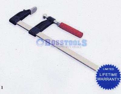 Image 2
Go to tool accessories in this next link if you can not see Image 3 copy this next link: http://www.bosstoolsupply.com/index.asp?PageAction=VIEWCATS&Category=381
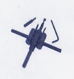
where they show the right picture of a twin cutter towards the bottom of the page "Cutting Accessories" this is the one we need. If you click on that cutting accessories they will show you a cutter with only one blade which is no good for our purpose since we do not use the drill bit in the center for support, thus the twin cutter works much better and is less dangerous on the final cut of the work peace, if you set both cutters the same. --------->
The sizes to have handy would be: 2 small spools #30 and #26 each. 1 - 35kg spool of # 23, #18 and #8 each.
The opinions vary here, but I give you what has worked for me so far. The most important points to consider are impedance matching to the batteries and coils used, range , transistor SOA curve, high RPM (many turns) for highest possible voltage spike and highest frequency equals lowest possible ampere draw. This is best accomplished by a stranded/lized long (more field less amps) wire by adding strands to a certain footage until 0.4 - 0.6 ohm is reached.
My coils DIA 3"x2 3/8" 75x60mm long 1" core. Exactly 300 ft approx. 500 turns 6 filer/strands 1 of # 26, 5 of # 23 AWG. We know that 1 strand at 300ft = 4.6 ohms 5 strands is equal to 1.1 ohm. To achieve 0.4 ohm we would need at least 12 strands #23AWG. The size bobbin needed for that amount with a one inch core would be close to DIA 4 ¼ x 3 ½ long =110 x 90mm. I know for sure, that 12 strands of 350 ft #23AWG, soldered as one, measures 1.0 ohm.
To buy a big roll of # 23AWG is probably a good idea. Stay with the 300ft wire length and once you size up just keep adding wire strands/lize to the multyfilar twisted wire to bring the impedance down like explained above.
Number 8 and #30 is also very helpful to have handy. By using #8 instead "K" copper you take advantage of the self-induction. Even a perfectly straight length of conductor has some inductance. Inductance has its greatest effect in AC current. Current in a conductor produces a magnetic field surrounding the conductor..... See: http://www.sayedsaad.com/fundmental/8_Self-Inductance.htm
Whenever you construct positive and negative bus bars or charging conductors, always design and cut them to equal length! If you bring two leads to one point, make sure the continuing conductor has a cross section of both wires! Watch the cross sections. The bus bars around your motor should have at least the same cross sections as the twisted coil wires added up measured from the coils, same with the charging cables. With eight coils using 1/8th stranded/lized wire, you would need a charging cable as thick as 7/16th" 11mm in order to match the impedance with the big batteries.
If anyone would ask me for advice, I'd say go, for the 12 lized 23 awg since it will be used most likely for charging car and truck batteries at the end anyhow, with the benefit of the matched impedance and probably not getting away with using BD234 bipolar transistors. For any motor drawing more than 3amps, use MJL21194's. Mind you, if you are planning to build several energizers, then something in between comes in handy for small batteries like my small four coiler with a max. of 3.2 amps at 15V SSG4a . The nice thing is, the lower the power source you use, the less current it will draw. The SSG4a is very flexible, it will still run and charge a small battery with an input as low as 3 volts, while in the other hand, it also will charge a 600CCA battery quite quickly at 12 volts.
For the ones that wish to use shorter wire. 6 filer 1 # 22 /5 #18AWG for the five strands is 0.8 ohm at 150 ft, where 1 strand = 1.5 ohm.
8. Twisting the copper wire:
Pick a tree, a fence, anything to tie your wires to, measure off 300 feet and mark it with spray paint or a peg, get rid of all the debris, place skids every 10 feet unless you want to play monkey climb up tree. String you wire with a little pulley, save yourself a trip or two, once you have them all cut and strung out, tie heavy objects at the one end of the wire of equal weight like rebar’s as an example, place your pulley on the wires by pulling and shaking them, or use a fish scale and place equal tension on every wire, this is how I get rid of all sagging wires before twisting. If you disregard this operation you will have wire loops protruding all over your twisted wire creating havoc to your impedance. Place an eye bolt in the chuck of an electric hand drill and fasten the copper wire by twisting through it. Let the drill wine by keeping the wire always nice and tout, first for a few seconds, then check the whole line making sure for the absence of debris and loose loops, otherwise flip the drill in reverse and fix the problem. Twist the wire until short by about 10 feet from your 300 ft mark and 5 feet (the 5 feet is acurate but the 10 feet keep an eye on the twists /inch) back of 150 feet, drive a peg in the ground, add a nail to it and hang the eye bolt onto the nail. Now take it out of the drill chuck. Place a new eye bolt in the chuck and repeat the whole procedure at the other end of the wire. Talk to an Electrician for an empty wire reel, Cut a stick from your hazelnut bush which fits nicely into your hand, drill a hole into the face end of it and fasten it to the side of the reel with a lag screw and wind the twisted wire unto the reel, using a broom stick or shafting to spin it on. Whenever you pre-drill for a wood screw, measure the thickness of the thread root and chose a drill bit slightly smaller than the root. If you use hard wood, add a little grease to the screw.
 Image 4
9. Wire winder:
Image 5
10. Filling the spools (SSG):
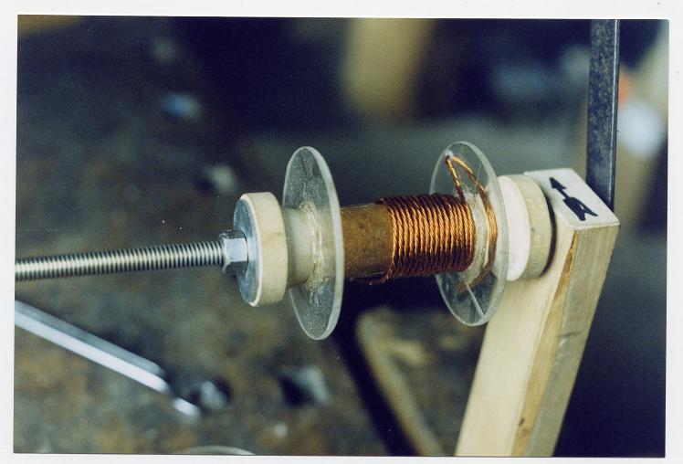
Take the reel with the twisted copper wire and clamp the shaft in a radial position into something a few feet to the right side from the vice, stick your reel with the twisted copper wire on the shaft for easy turning and clamp the wire winder into the vice, see picture Image 4 - 5, take a felt pen and mark the top of the winder with a clock wise arrow for a north oriented right hand rule coil. For the North Pole orientation, use your felt pen and mark a big black dot besides which you Drill a small hole close to the edge of the acrylic disk for a small copper wire to tie down the main wire..... not like I did, don't take the big wire out of that hole, it gets into the road of the spinning magnet...... and start winding.....
I know John Bedini is not worried how the wire is wound around the bobbins, in this case however, a neatly wound coil makes for a nice tie down and smooth gap adjustment.
11. Right hand rule (North Pole)= grab your spool with your right hand, holding it in front of you, thumb up, which is the north side of the spool with the direction of your curled fingers being the direction of the wire wound, from the thumb towards the small finger. Keep in mind that a positive source of recognized ether waves invariably acts from a north to a south pole, just as the water flows counter clock wise down a sink drain (if undisturbed) up here in the north hemisphere anyway. The dots drawn on the windings of the spool Image 5 JB' drawing and Image 7 below indicate the polarity, meaning in John's case, you wind the motor and trigger winding as a two filler clock wise being a north pole (right hand rule), then (for an SG set up) on top of those windings you add the third wire cranking the coil winder counter clock wise, since it is south oriented on the north pole of that specific coil.
If you for some reason do not know or can't see which side of the coil is north oriented, then touch the two coil leads to pos. and neg. battery terminals while holding a compass in front of the coil, turn coil until south needle of the compass is pointing to the coil core which would indicate the north pole of the coil. The reason why it is not the north needle is because like poles repel each other. You will find that the lead you touched the pos. battery terminal with, is the north lead of the coil, if you have used the right hand rule, otherwise the opposite would be true.
12. Coil cores:
John Bedini uses Lincoln R60 AWS R60 1/16” 1.6mm Number ED025401 copper coated, oxy-fuel welding rod or cast iron, I finally just learned. I use 1/16 tie wire. When I was eager to find out what wire to use I could not get any proper answers from the local suppliers and when they did sent me $ 60.00 worth, the rods where retaining twice as much magnetism as my tie wire did. I still have all the rods and never used even one. As long one is not heading for utmost performance, the core material is perhaps not so important in this SG arrangement. John Bedini long said that the secret is in the collecting and switching of the wires, which I could clearly see in my new SSG 6b using the JB /RC switching schematic. Anyway, I clamp the end of the tie wire into the vice and unroll 15 feet at a time, cut it and stretch it with a pliers with the one end clamped into the vice. It takes about 5 lengths to fill a 1" core. I made myself a little jig clamped down in front of a yogurt container (I eat yogurt) with a rag inside as a cushion, thus I cut them a 1/4" longer than the spool all to length with a side cutter, a few more than needed, bundle them up with a wire and place them in the hot wood coal for 10 minutes, then placed on top of the oven on a fire brick and let cool over night. The next day I clean and lacquer them. If you don't like the hot coal and lacquer idea, just place the wire in a warm area and wet them down a few times until you have nice layer of corrosion built up, which will do the trick too. Then I load them in the core of the coil and hammer the last ones in nice and tight, some glue for safety at the south end. Then I mark the coil for top on the North end at a 90 degree angle of the rotor radius and grind out the proper radius on the stator wire core with a bench grinder, a hand grinder will do the job too and check it with a proper radius template and straight edge for squareness.
Image 6
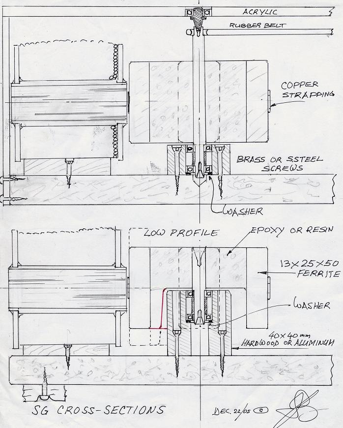
13. Energizer / rotor Base:
3/4 x 12 x 12" particle board melamine finish (shelving material) for main base. For cushion feet , talk to some one in a tire shop that works on logging skidders for an old inner tube (rubber is about 4mm thick, you will need lots of it, you can use it for all kinds of things), cut 12 1 x 1" squares and punch a hole through them (punch tool, usually as a set in different sizes or pliers type Revolving Leather Punch ) place onto a # 6 x 3/4 wood screw, pre drill and mount under the four corners of the main base, tighten until head of screws no longer protrude.
14. Bearing assembly: Use 3/4***(less 1/8th) x15/8 x 1 5/8" 19x40x40mm birch wood or solid round plastic or aluminium. Bore two holes in line or either end to take 1 1/4 brass screws also one 5/8 hole into center of the flat side with a spade drill for two bearings and a copper spacer/bushing with OD of either inner or outer bearing race. Cut off from brass tubing or plumbing stock used for sinks feed. Place into chuck of drill press set for high speed and cut to length with a file, thus you have it nicely squared off. 3/4*** is the approx. height of the standard rotor use different measure for the low profile and make sure that the center of the magnets is about 2 - 3mm lower as the center of the coil core this will create magnetic lift taking the weight off the bearings. (Consider same tolerance in the top bearing life center!!) The bottom bearing of my two coil 5" rotor hard-drive assembly, dropped out one day, didn't know 'till I stopped it. Have no idea how long it ran with one bearing only, get this: no top support, which means the rotor ran like a gyro, guided in the magnetic field of the stator cores and magnets of the rotor itself. This even works with a one coil set up, hence the oiled play in the bearing does not seem to matter once sufficient RPM is reached.
Take a pencil and mark the diagonals on the white shelving base. Mark the center of the x with a punch and drill a 5/16" or 8mm hole1/4' deep for clearance of the shaft. Set the predrilled 3/4 x1 5/8 x 1 5/8" 19x40x40mm birch wood into center of your marks, drop the 1 1/4 screws in the holes and hit them slightly with a hammer, predrill according the root size of the screws and tighten screws. Drop a washer in the 5/8 bore which center hole is slightly larger than the small bearing race***, slide the bearings with the spacer in the middle on the shorter end of the yogurt rotor and stick the bearing assembly in the 5/8 bore. If you used a sharp spade drill, the bearings should be nice and snug, if they are to loose, mix some fine saw dust with Carpenter’s Glue and build up the bore slightly, stick the whole thing back in, check for squareness and let dry. *** When ever you mount a bearing make certain that the outer race takes the weight stopping on the washer or shoulder of the press fit and the inner race does not touch the bore so it can spin freely. This is some times the reason why some people have friction problems.
14a. Oiling lower bearing
Before you stick the lower bearing on the shaft, remove the rubber seal permanently. Oil the bearing with a wire (drip oil down the wire) through the bore of the upper bearing or drill a diagonal hole into the bearing assembly gluing in a plastic tube out of ball point pen.
A way to permanently oil the bottom bearing or both of the assembly is to keep the bore just 3 to 5 mm deeper than the bearing and remove the lower seals, that way no dirt can get into the oil as long the rotor shaft is in the bearings and you can control the amount of oil by removing the rotor.and dripping oil into the bore.
15. Birch wood:
Is a nice hard wood to work with. If you acquire some green wood, place some cuts length wise the trunk for the bark to curl, thus it will dry nicely, otherwise it will suffocate and rot. Let it dry for a whole season before using. Cut into boards and stacked between spacers and season it by air currents is best. If you are hard pressed and in a hurry, you might find some nice dry chunks at a fire wood sales and get them squared up by a friend who has a table saw.
16. Mount coils:
Place coil in front of the "Yogurt" rotor and measure from flat base to center of rotor, measure from base to center of coil +2 to 3mm and take the difference which will be the thickness of the base you will build next. Every base has to be fitted to each coil since every coil has a slightly different contour line. I use a 2" drum sander (the fine saw dust makes a handy glue additive for building up things or covering cracks) and the drill press and cut out a radius that fits the coil usually in two steps since the last layer of the windings stops in different positions away from the north, meaning about 1/4" 6.5mm space to slide the coil pack and forth for the stator/rotor air gap. If you wind the wire onto the coil cris-cross, the coil will get bigger and you need to use a flat base with wedges and rubber padding, (does not work as good). . Once I have the coil fitted to the right height, I drill a small hole in the center of the base and counter sink the hole so the little head of the screw is flush with the top and lay it on the diagonal with the coil touching the magnets with 1/8th" play, this way you can always pull the coil back for gap adjustment, take the coil off and mark through the hole of the base with a center punch and make sure the mark is in the middle of the diagonal and then predrill for a half inch brass screw. Cut a strip of inner tube rubber, covering have of the circumference of the coil and place on top of the coil and base if needed. Take a measuring tape and measure from base to base over the top of the coil and cut that much off of your 1/2" 22 GA. copper strapping roll making sure you have an odd number of holes for equal length, because the center hole of the strapping will take a stainless steel oval taper head machine screw #8-32 x 1/2" sticking up for the heat sink of your transistors. Bend the ends of the strapping to a 45 degree angle, hold it in place, square in the middle of the coil if possible and mark both sides on the base for accepting the brass screws. Remove the coil and predrill those two holes on a slight angle with proper drill bit size by measuring the root thickness of the screws you are using. Install the whole thing incl. the stainless screw and tighten slightly, adjust the air gap between rotor and coil to 1/16" 11/2mm and tighten. I use mainly #6-32 x3/8 pan head stainless steel machine screws for all the transistors and other mountings.
Cover all your batteries while charging, very important for safety, hitting a battery with too big of a voltage spike or spark might be enough cause to explode it!!! Meaning acid everywhere and possible injury, so better be save than sorry.
17. SSG John Bedini Circuit Schematics Illustrated
18.Transistors:
The 2N3055 Transistor has the terminal arrangement different as the BD243C. If you hold it with the holes in a perpendicular line and the leads pointing at you with the off set position down, then the Base is on you right, the Collector is the Case and the Emitter on the left.
I do not use transistor insulator grease and pads. I mount the transistors directly onto the heat sinks with the good conducting slicone grease.
Check the transistor with your VOM +lead and - lead as follows:
C+ and B- = 0 B+ and E- = 0.545 ohm E+ and B- = 0
C+ and E- = 0 B+ and C- = 0.537 ohm E+ and C- = 0
Make double sure by using two different meters...sometimes you might get a reading of say 0.12 when it should read 0.00 meaning it will be half gone, you can chuck it. Once you have the transistors soldered in place, repeat the whole measuring exercise and mark everything in your lab note book, it will help you tremendously in trouble shooting your electronics. IRFP260N are N-channel power Mosfets which I replaced two out of four in my 1500 watt inverter, they look just like MJL21194 NPN Bipolar Power Transistors, but measure with the positive VOM lead 0.545 ohm on the right collector terminal instead, whereas the other two terminals masure 0, holding it like described in paragraph 17. The smaller IRF630 Mosfet measure the same.
20. Soldering:
I use a 240V Iron which has a solid round 7mm copper bar, from the old country. I use it 95% of the times for all work I do on the motors, except in tight places. It is very fast in melting the solder, thus the heat does not have time to pass the clamps. It is especially handy for unsoldering transistors out of a board by heating up the solder connection and blowing the solder out of the hole with compressed air, (they just fall out, then use a sharp piece of hard wood do clean all the blown solder off the board). Using good Heat Sink Clamps is a must of course where you can use them, otherwise apply heat to the board first and then touch the transistor terminal quickly, when soldering them back on. Use Rosin Core Solder only. Use a small torch to burn the plastic coating off the copper wire and shine up with emery cloth. Before you solder transistor terminals on heavy copper wire, apply some solder to the wire first and make sure you have a good bond, other wise the solder will come off the copper and the following arcing will ruin your transistor.
21. Silicone Grease:
Is a water repellent, non-melting, dielectric grease lubricant. Use it on all your heat sinks at the bolt on copper and transistor surfaces for a corrosion free and long lasting good conductor.
22. Batteries:
See my comment about Batteries on my 5th page
Switching Power Supply
I found it convenient having a couple of 12V 18A, 350W output rated computer power supplies handy (for 50 Bucks each) for both my SG's and computer, in case my computer PS brakes down. If you buy one just look for the green wire in the bundle and connect it to the chassis, otherwise it wont power up on the outlet. Always shut it down first before the SG. On my older 12V 10A SPS I de-soldered all black (-) and yellows (+12V) wires off the PC board and replaced them with one 14 gage each.
With the SSG4a in Image 4 next page, I am using an open switching (computer) power supply 12V 2.5Amp with an output of 11.6 VDC, using a Happy Days Goat Dairy milk container for a wind tunnel. Note: There are plastic covers in front of some of those 12V square fans, which are removable for oiling (adding oil and Protec or XL+!!) This is a must if you want full and lasting fan power. Cut those wide bars off the steel boxes, in front of the fan and replace with wire mesh. Because of the good cooling I was able to draw as much as 3.5 amps out of that 2.5Amp unit without damage once.
24. Power Supply and charging small batteries:
I use a DS-304M (very reliable unit) adjustable power supply from 0 - 15V 30 AMP which gives me enough flexibility to charge any small size battery with the big benefit of being able to choose the exact voltage for charging every individual size. I have actually charged little hearing aid batts successfully, having made a holder to charge five in series at once (mind you there is only one type that will charge up to 1.9 volts (surface) the others usually won't give or they just pop) with my SSG4a 4 coiler (performer, 2 x 3 1/4" yogurt rotor) at a motor input of 2 volt cutting the RPM way back as a result and still having 11.5 VDC charging. In the past I had some of the smaller batteries pop on me (messy business), because of this charging interruption, I started to use a 115 Ohm 3 Watt resister in series with an LED to protect the transistors, not that I have lost any transistors because of it so far, I do use the neon lamp even on the Bedini/Cole switching.
I changed my electric shaver right from new, cutting the 110VAC cord for SSG hook up and changed some of the wires around going to the board and AA-NiCad battery, using * the DS-304M variable PS , set at 4V in 1.4V out for 50 to 60min. settling to 1.35V. 2 -D cells set at 8.5V in 5.4 out for three hrs charging to 3V. 4 - D cells set at 8.5V in 8.9V out for six hrs charging to 7.5V. Any components that use wall mart chargers, I install a couple of banana jacks bypassing the components hooking up directly to the battery terminals. *If you build a small SSG you can probably get away with using a 9VDC / 12VDC Power Wall Adapter which must be at least 1 amp per setting.
Image 7 (SSG) See my very first replication as Image 1 on my replication page.
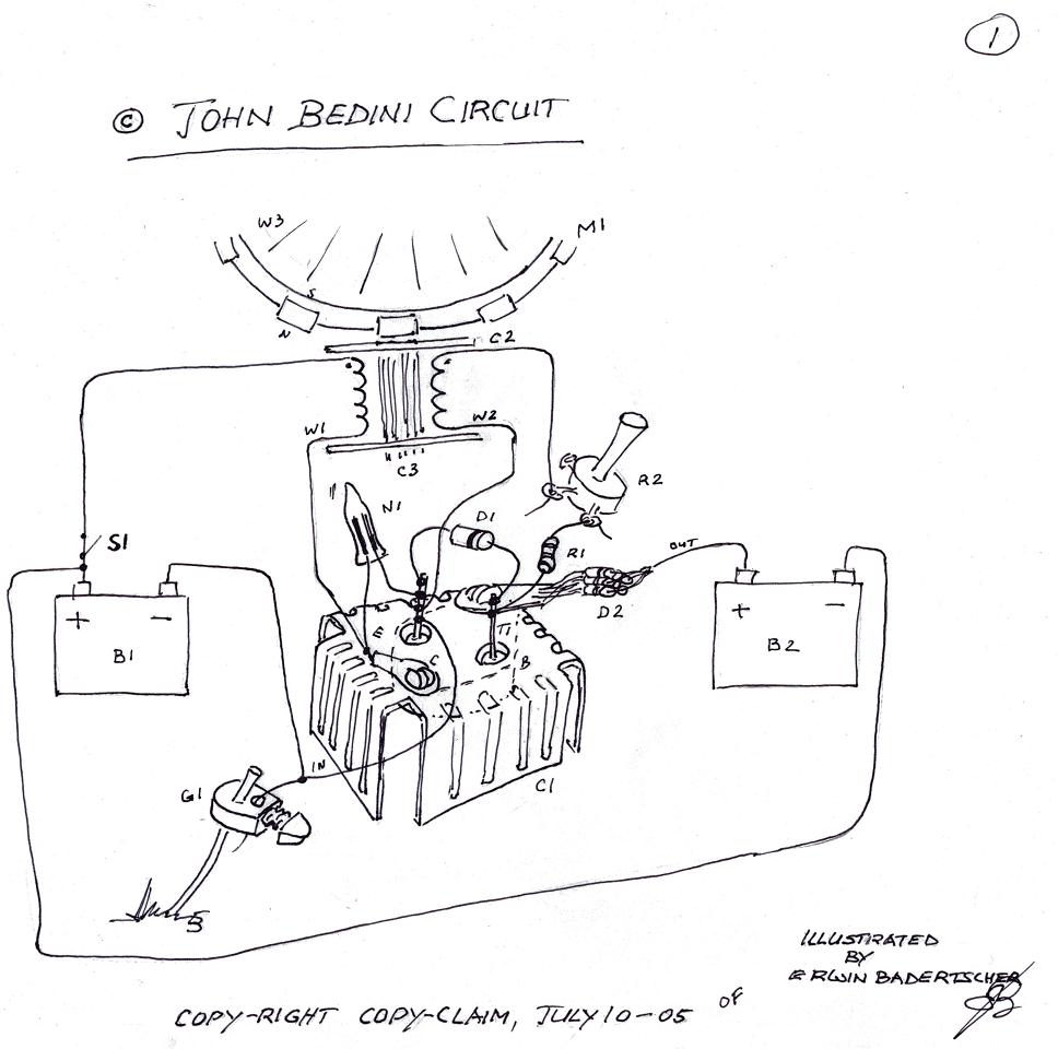
Image 8 (SSG)
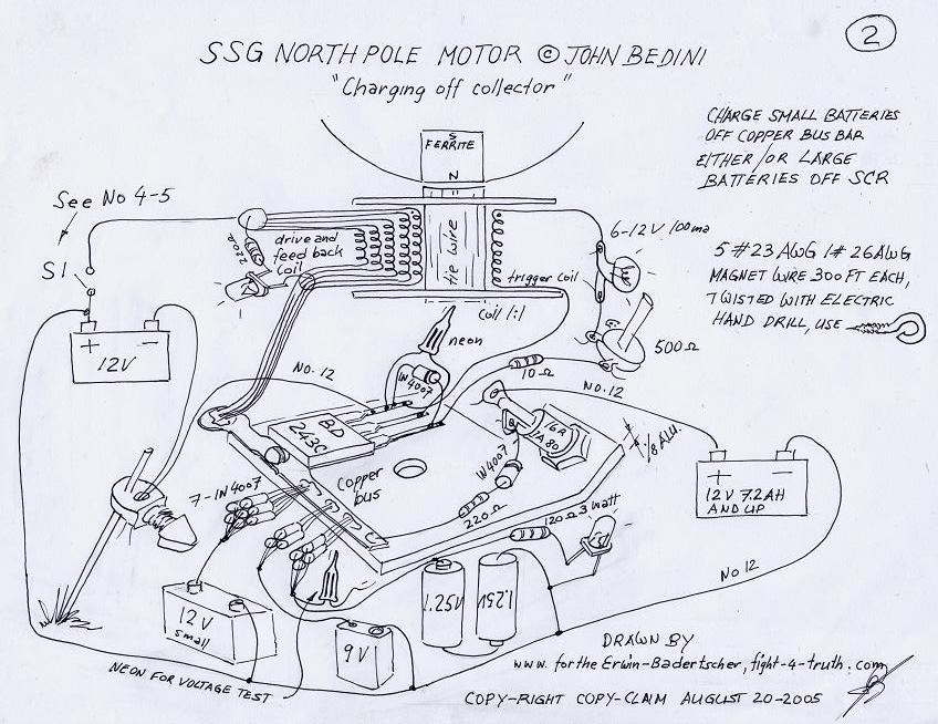
26. Start up:
Did you hook up the charging batteries, because if you haven't, there is a good chance for damaging the transistors, even if it is just chipping them, never rely on the neon bulb. It is a safety valve, which is about all.
Clip the negative pole of the coil to the emitter of the transistor going to the batt negative. Take the north end lead and flash-touch the positive terminal of the batt, if the magnet of the rotor is repelled, you got the set up correct and if the magnet is pulled in to the coil core you must reverse the coil leads. Do the same things again, only this time, look for a spark while you touch the pos. terminal of the batt. If you have a spark, the transistor is biased on, turn up the pot anywhere from 180 to 400 Ohm (use 2-3 watt resistors) until the spark disappears, if not, you have a burned out transistor. If you have an LED in parallel to the windings it should also momentarily light up when you flick on the switch. It might even stay on with a buzzing sound, the moment you give the rotor a nudge it will change to interrupted sounds. If the rotor is barely and harsh running, voltage is sucked down and amperage is jumping up... you have a dead short --->transistors. If the SG suddenly quits and is dead, you have a wire shorting out somewhere. If the neon lights up you have no connection to the charging battery. The neon should never be on.
Once you have rotation, read: Tuning a multi coiler not quite halve down the replication page.
You can only charge from one source at a time, either through all three diode connections off the collector or
through the SCR! Charging little batteries takes sometimes small assemblies where clips slip off, batts fall out, batts pop etc. therefore it is always good to clip an LED across the charging wires to protect the transistors in case the circuit at the batts should open for whatever reason. See the drawing above, where such an LED is connected in parallel with two 1.25V NiCad’s.
Cone start: Once you are a little more advanced needing to start a self runner, then use an RC (radio cotrolled air craft) starter cone and 12V starter motor or hand drill, instead a pull cord. Spin an in- or ouside alu.cone onto the SSG shaft and start the SSG with a rubber shaft or for the RC prop/turbine cone use a rubber ring driver from your RC days. :)
27. Capacitors:
While you are checking out a solid state board to test caps, place or clamp it in such a way, that you do not have to touch it once you plug it in. Put on glasses, because they have a tendency to blow up out of the end of the cylinder body.
If you unhook the battery charging lead before the SG rotor comes to a full stop, the caps will collect enough voltage to shock you if touching both cable ends!! The spike alone can give you a hefty shock, if you don't pay attention to what you are doing. Also having the SG hooked up to a Power Source , even though everything is shut off, the high voltage caps of the PS will slowly bleed off through the negative lead into the SG caps filling them!!!! Be alert!! Don't touch things without thinking!
28. Alteration
For an example, let’s look at my new Philips shaver which I bought just for that purpose. Some day I will not be able to buy shaving soap anymore, hence my decision for the rotary stubble cutter.
I cut the 110V cord 3" from the plug on the shaver side by a 1" step making it impossible for the two ends to ever make contact (banana plugs is another route). Then I marked one side of the plug with a red line across into the shaver body for the positive conductor and also the longer end of the cutoff. With a 1.8x40mm Torx driver I unscrewed the two screws which held the case together. Discharge the 385V caps with a 4 watt resistor or a lamp by holding the resistor with insulated pliers pocking one lead on top of the capacitor which is the negative and the other lead touched the positive of the NiCad battery and lifted out the board (sometimes you run into caps that are enclosed with the negative not in reach, there is usually a solder spot provided beside the cap on the board instead, where one can short it out). I unsoldered the plug fastened to the board permanently. On the same side of the plug lead, lining up with my red mark on the outside of the housing, I soldered a bigger red wire taking it along on top of the board to the end and down under connecting up with the positive of the motor and battery soldering spot. On the negative side of the plug I fastened a green heavy wire one inch longer as the red one to make up with the one inch I lost on the cord and fastened it to the negative solder terminal of the battery under the board, installed it all back and hooked up the VOM making sure all is well. Read the 6/5/4 last lines of paragraph 24. Some times later, I added another Ni Cad in parallel since there was enough space on the board. I soldered on a small drop of rosin on both sides of the battery, added a red and green wire each side just long enough to reach the terminals of the battery beside it. With my jackknife I carved down the ribs on the plastic cover making room for the new cell. In the process I broke off a tiny nob on the unsteady plastic sled-switch which rendered it useless, until I fixed it with a drop of E-Z Super-Glue. It made quite a difference to the performance of the cutter. Before I start up my energizers charging any battery, I always hook up a voltmeter confirming proper hookup, charge rate and voltage. I seldom walk away from the setup before physically checking temperature of resistors, heat sinks and coils.
Cover all your batteries while charging, very important for safety, hitting a battery with too big of a voltage spike might be enough cause to explode it!!! Meaning acid everywhere and possible injury, so better be save than sorry.
30. Carbide/Tungsten/ and glass cutting
Bottles can be cut on the tile saw, or with Oxy. Acet. torch set to low gas pressure small nozzle and small sharp cool flame (whispering blue short core, not yellow), use turning platform (SG), floppy disk drive, or record turn table, balance with sticky reservoir or septic tank sealant/caulking strip, turn the bottle slowly and steady, apply heat to ink mark with a steady aim to the line in intervals and irregularly but close up, play with it but quickly, to shock the glass... glass will snap off evenly all around in a few seconds, if the flame is too hot the top part of the bottle will shatter and you won't get a clean straight break. If you apply steady yellow heat the bottle will just warm up and you will end up frustrated!! The hot wire method did not work for me on the rounded neck of the bottle.
Clean up the cut glass on a belt sander or sanding disk on your handgrinder and wear a mask.
31. Spark Gap
Silver solder a carbide bit/chip or building up the copper tip by dipping the rod into tungsten powder or get somebody to trickle the powder over your melting bronze. (Wear proper goggles) SS or round headed Brass bolts,
Carbon/Graphite (welding supplies (air ark) and thoriated tungsten rods are used for spark gaps.
Safety gap: Take an old 3/4 by 1 -3/4" bearing (seven balls) and cut the outer race in half with a torch, place the balls on top of 1/4" nuts and tig weld them onto the nuts. Of course you can buy those rounded nuts too.
Gap of 1.4mm = 1000V which spark is found by slowly cranking up the pressure. :)
The sparks of the gaps are very noisy, enclosed and air vented under slight airpressure with big magnets added is best solution when using Tesla cone transformers.
Tesla Cone Transformer Patent No. 593,138, November 2, 1897:
I cut a 6” / 153mm disc out of a ¾ “ / 19mm board and marked the circumference into 32 segments, drilled 1/4 “ hole in the center and placed a 1 – ¾” bolt with washers and nut in it, good and tight. Out of the same board I cut an 1 - ½ “ disc and marked it into 4 sections.
Then I ripped some 3/32 / 2mm stripes off of the board to make 32 ribs for the cone. Since the ribs are only 1mm or so apart on the top disc, they must be tapered on the ¾” top side, otherwise they won’t settle in properly on the top at the time of the gluing operation. To get the correct rib sizes, the cone is drawn onto a cardboard with all the angles with the cone side measuring 155mm / 6 - 1/16 “, which is the surface the #30AWG magnet wire is mounted on.
I used crazy glue to glue 4 ribs in, starting with no. 1 and then 3 more at 90 º
Or the cone is placed in the lathe chuck and life center and trued up. Then I glued a #23AWG wire around the top edge to hold the copper wire from sliding off and a little nail as an anchor for the #30AWG. Then Carpenter’s glue is applied in short sections (to prevent it from getting to tacky) to the rib surface. I wound about one inch of wire onto the cone then cleaned the squeezing through glue off the copper with a wet sponge, before I proceeded adding more glue onto the ribs. The wire is wound from the narrow end towards the 6” disc side with the lathe in reverse giving me a right hand north polarized coil, because it is the south pole of the coil which I am starting from. As the secondary wire is fed onto the slippery surface it slides into place nice and tight. This can be done easily by hand with somebody cranking the cone off a bearing in a board, it just takes longer. If you can arrange the wire being fed through a pulley under spring tension there would be less danger for the wire to snap off.
I used some 1 - 1/2" tubing and angle-iron-setup for a guide to push the pulley along guiding the wire up the cone. The winding assembly was bolted onto the tool post of the lathe. I cut a peace of the tubing, parted it in half clamped it onto the tubing and welded the seams shut, it worked great for a slide. For the 21/2" sheave/pulley I used 1/4 " flat aluminum and pressed a small bearing into it. The one on the photograph was to small, I had to change it for a bigger one. The V-groove of the sheave, about 1.5mm deep, must be shaped like a halve current sine wave http://www.sayedsaad.com/fundmental/5_Sine%20Wave%20In%20Phase.htm with a nice radius to the edge of the sheave. This way the wire angle running off the spule matters little, because the wire keeps sliding along the pulley grove and radius without jumping off.
If you happen to break the wire, slide a shrink sleeve in place before you solder the two ends up nice and parallel. If you wind the wire onto the cone by hand, place the cone horizontally in front of you with the 6” base at your left while turning the cone clock wise feeding the wire over the top surface.
Resin coat is next...hold off with the resin coat 'till further notice. Then glue five ¼” / 6mm wood blocks ½ “ / 13mm from the bottom to keep the two turns of #8AWG primary at the proper air gap, then the wire is temporarily masking taped in place beside the blocks and 5 - 5/8” / 16mm x 1 – ½” linen cloth strips are cut for the saddle straps of the primary and held in place over top of the wood blocks with two coats of resin.
Cone is bolted onto ¾ shelving board. A 160mm x 1/8th shrink tube is slipped overtop of the secondary and glued with hot stick (glue gun) from the top of the cone to the base and soldered onto an isolation fence, same with the polarized end.
The amount of secondary wire is found by equal weight of the primary. If the primary wire wound twice onto the cone has pigtails of 3” or 76mm, the weight of the secondary works out just right, if you follow my measurements.
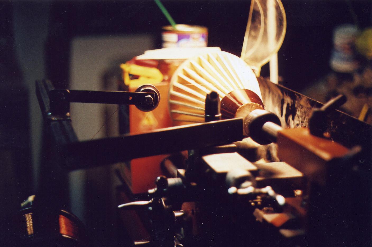
The main reason is safety and trying to keep it as simple as possible, in case you wonder why I don't just stay with the ED Gray tube. I can move the high voltage of electrostatic induction or electro-radiant energy, safer from one building to an other with the cone setup, because of the earth grounding plates on both ends. Even though the current is suppose to be a pure aetheric stream, Tesla still cautioned and was talking about security. The other is I think I can create higher Voltages/aether currents with the cone for less work done. Perhaps for the same reason Nikola Tesla left the frictional machine and Leyden jar behind and developed the Cone-Transformer or induction coil of peculiar properties. Cones are fast cheep and easy to build, once I have the Motor-Dynamos with the proper output, high frequency and short impulse setup with duration of less than 100 microseconds. With other words, I'll know more a little further down the road. :)
Image 9a
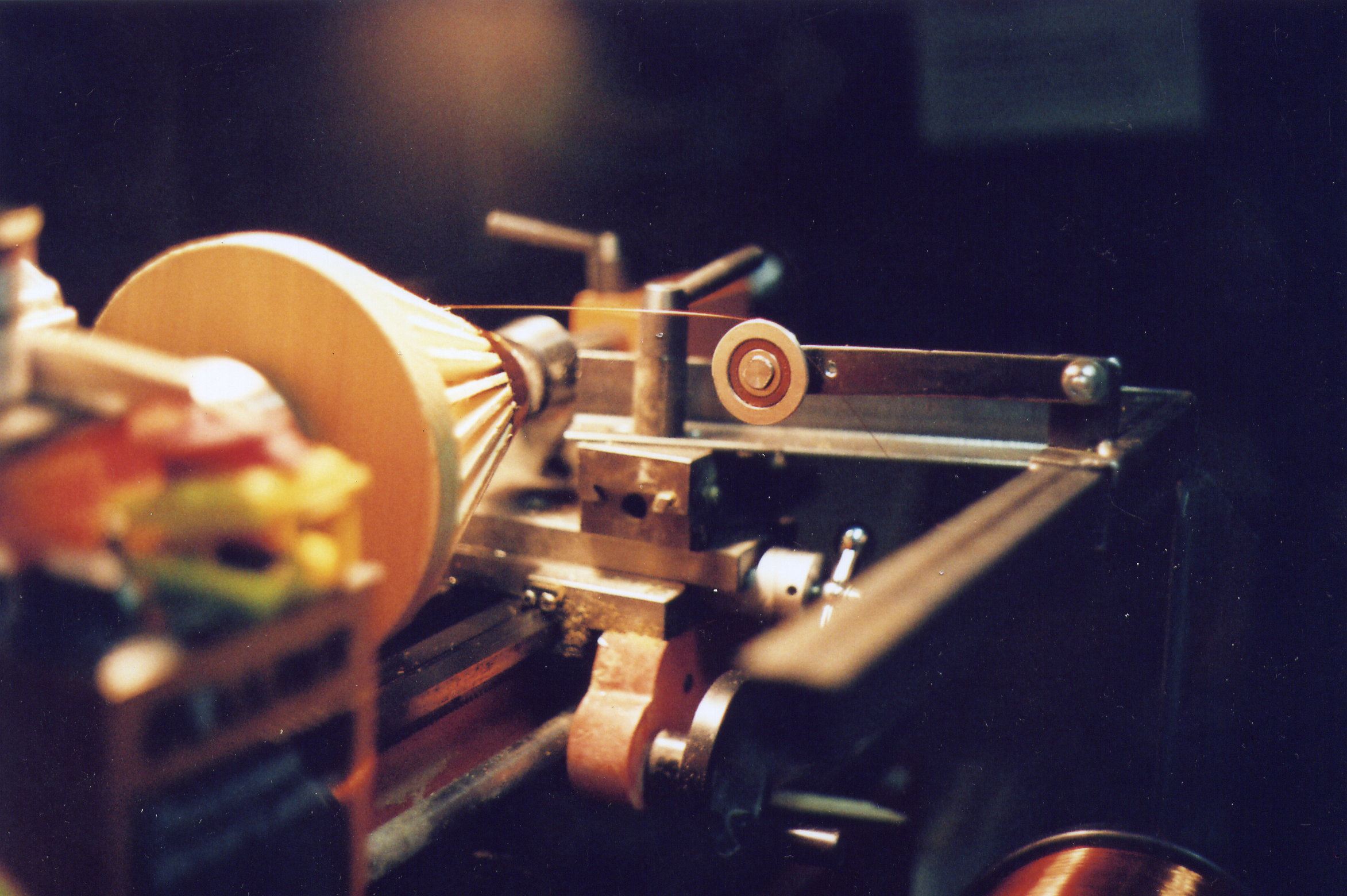
40uF 5KV Monster capacitor!
What we be using the big cap for.......does it have an application in the Bedini set up, or is it just for fun?
Both, Bedini and fun!!!
It is entirely depending as to what you
are steering for, charging batteries only or serious Home Power.
The Idea is to get into cold, save
and radiant electricity by creating explosive radiant
electrostatic fields of spatially-distributed voltage which is picked
up by Ed Gray’s tube, through Tesla’s secondary high frequency trafo’s
or Bedini's magneto and stored in big caps of 10uF minimum to do work.
You heat your house and or you can run a
large electro motor driving a 240V 60cycle generator for your house
power needs, like I hinted above, there is many ways to use this
radiant HV. Aether energy you can get with any high frequency apparatus
switched with the Bedini
circuit storing it in big
caps instead of burning it up or Edwin Gray's charge-receiving-grids-conversion-element-switching-tube fed by
5KV caps from one side and 12/24V with commutator (unidirectional
current) from the other. Power is raised in Gray's setup from the
battery via an inverter filling
the 5KV caps to 3000 volts DC, or your own self running magneto.
I suggest you buy Peter Lindemann’s book
“The Free Energy Secrets of Cold Electricity” http://www.free-energy.ws/products.html
If you read that from cover to cover it will give you a good shot in the arm!! Bedini's Ed Gray schematics are in the back of that book. You will understand my Schematics page a bit better also.
Benchtop Drill Press
The bigger the throat the bigger the disk work peace you can machine on it. If you buy a used machine make sure the radial main spindle is within 0.001" or 0.025mm slack on its axis. Test it with dial indicator. If you don't have one, then buy one, because you will need it many times to come
If you have a 16 - 1/2" press you can boar a hole into the center of a 16" Lexan work peace, fasten it to a mandrel/arbor tighten it into the drill chuck and machine it true to a 16" diameter. The cutting tool is clamped onto the table with the platform locked, whence the spindle with the work peace is slowly lowered onto the cutting edge.
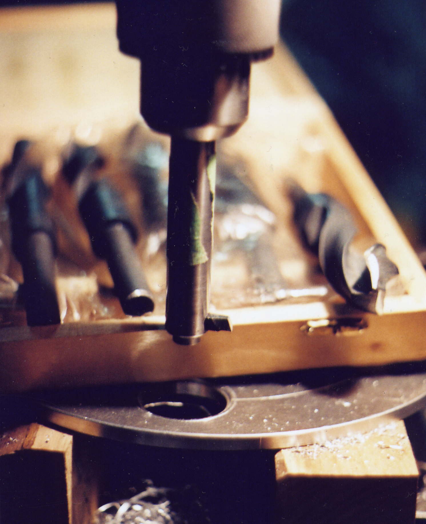
Wanting to drill an accurate bore bigger then 1"? Take a 3/4"/19mm round rod and drill a 5/16 hole 1/4 or 3/8th " from the end with 1/4 threaded bore into the face of the rod with 1/4"/6mm set screw to hold the 1/4 Hi-Speed Steel bit (HSS), see Image 9c and d below of this bar and set up along with a sharpened drill bit example, besides my drawing below, giving you an idea what I am talking about.
Image 9b
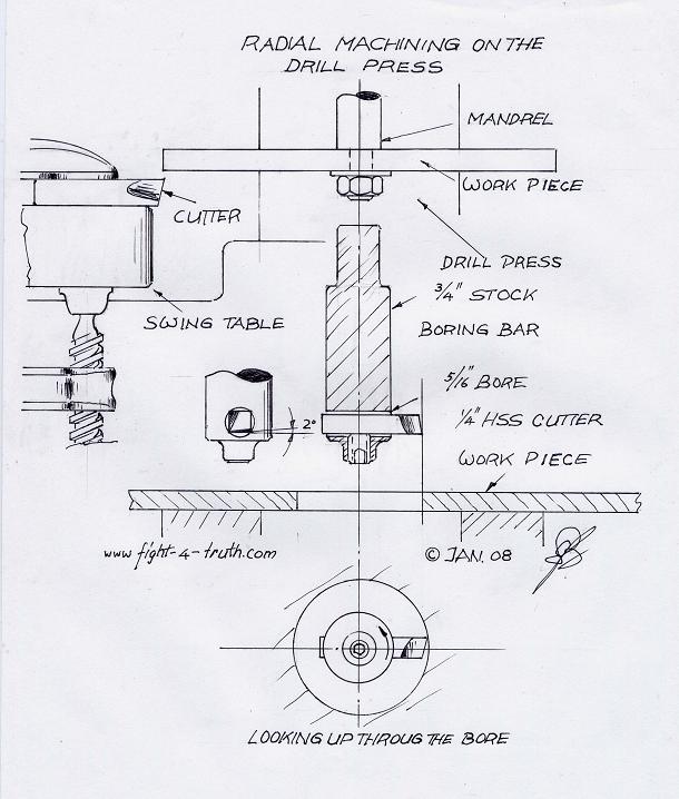
Image 9c
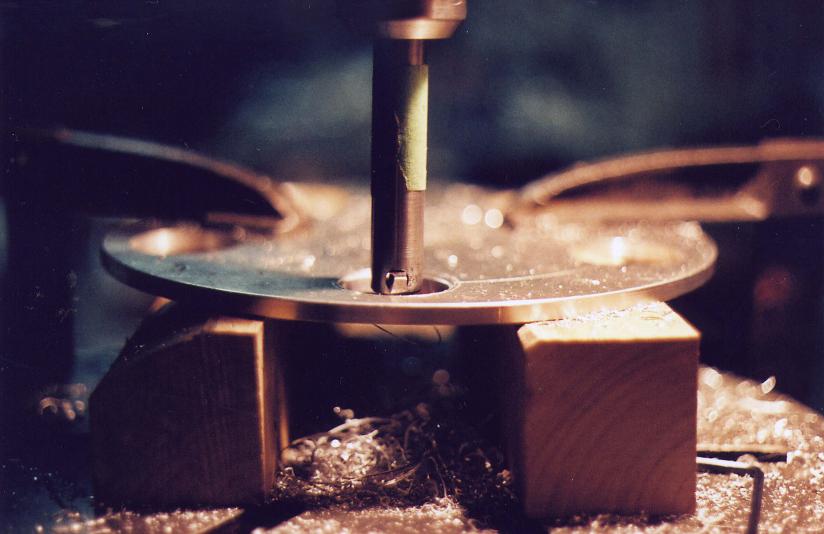
Center the work peace with a 1" spade bit, I use a center punch which I machined in the lathe, drill hole, replace with the boring bar and set the 1/4" tool-cutting bit to 30mm for the 30mm bearing to slide or press-fit. Press fit for Lexan 0.001"/0.025mm. For aluminum only 0.002"/0.05mm, heat up with torch and drop the mag's into the holes (but remember the flux currents with aluminum). Use micro meter and memo pad for the different bore diameter settings or make yourself three or four cutting bars. If you aquire a box of cheap carbon drill bits on the market it will come in handy do drill up a 1/2" hole in 1/16th increments into one inch diameter bore of aluminum. In order to prevent chatter you'll have to grind the free or relief angle of all drill bits slightly down to 1º making sure not to change the 118º point angle, use gage NO. 1. You'll have to do this very carefully on the bench grinder. Make yourself a gage NO. 2 out of 1.5mm steel plate which you hold onto the twist cuttingchip surface angle of the drill bit against the light watching your progress. This is best done while you in increments are drilling up the 1/4' aluminum.plate towards the press fits of the magnets or bearing races. Very gingerly start the big drill bits on the bore. If you have done it right you'll get a smooth cut and chip without chatter right off the bat, perhaps with a slight squeak meaning part of a free angle at or near 0º to the cutting edge stopping the bit from chatter. While grinding the bit, continually measure along the shank to the cutting edge for same distance on both sides, very important for equal cutting depth. If the drill bit stopped the chatter but also the cutting, it means you have 0º free cut angle on both cutting edges. Sharpen the drill bits on the flat side of the grinding wheel not on the front radius... Good self discipline and concentration exercise :) For sharpening dull bits use an curving action off your wrist on the relief angle of the bit If you can get it to work for you then you learned how to sharpen drill bits freehand, which very few people are capable of. Before you start with the sharpening process, study the drill bit root picture and angles form the top (tip view), see picture below, and keep comparing your work with an untouched drill bit in order to maintain the same shape and web angle exactly.
Image 9d
Shape your own HSS or drill rod cutting bit
Don't have a long enough boring bare for an accurate 1" bore? Then take a 5/16 HSS round bar or drill rod (silver steel), heat up one end little more then cherry red and form it on the anvil or chunk of rail tie into the desired shape by widening working it flat and turning it over bending it slightly on the anvil corner for the cutting edge. Grind the proper cutting, chip, back and free angle to it as shown in Image 10 below. If you see a worn out or broken adjustable wood drill or other cutting tool on a flee market or garage sale, grab it because the shank will be carbon steel for a good boring bar.
Not sure whether it is HSS carbon steel or just round rod? Stick it in the bench grinder and watch the sparks fly. If the sparks are dull red and just a few semi white it is hot rolled or cold drawn steel, although you see plenty bright white stars fly (burning up carbon) it will be drill rod (silver steel), compare it with one of your broken carbon drill bits (cheap bits). The sparks of HSS high speed steel are mainly dull red.
Hardening the cutting tip: Heat up tip equally to cherry read without burning the tip (more then cherry red is burning it) then quench in oil by stirring it around in the oil 'till cool, if you can still work it with a file you picked the wrong steel.
I found that those yellow twist drill bits, meaning coated with Titanium nitride, have a more narrow cross section on the twist then the black quality ground HSS bits do, the work peaces continuously get sucked up out of your hand a long the drill bit, quite aggravating to say the least, plus the ones I have are very low quality alloy, meaning the bit gets worn down on the shank to the next size! Also the black ground HSS bits usually come with better quality alloy which is the reason for the higher cost. Carbon steel drill bits have been sold to me on eBay advertised as HSS, consequently I will be careful from now on what I purchase from there.
Never let drill bits get hot while drilling, always use cutting/cooling fluids even if you just use a squirt bottle is better than nothing. Make it a habit to adapt the RPM to the drill bit size you are using, always slow RPM for bigger drill bits.
Image 10
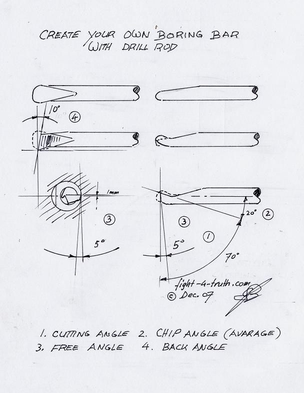
Cutting a thread into a work peace is best done by chucking the threading tap into the drill press and idling the cutter into the bore (see drill size on thread chart) of the work peace after flicking the motor on and off, thus the cutter is started nicely and square in the bore, then finished cranked by hand tool. Always use a couple drops of cutting fluid like New Rapid Tap (ozone friendly), it is especially helpful in Lexan plasic applications with less stickiness and smooth cuttings, it makes the thread look nice and shiny.
Lead
Soon or later
you'll be in need for some lead.
I took an 800CCA battery apart this winter and melted the lead down. It
is a messy job but beats buying the lead.
To get rid of the
acid I
neutralized it with
garden
lime; better is Type S (lumber mart), which the masons are using, it
works the
best. I
use it a lot with a brush and little water until neutralized,
especially after charging a battery. I actually neutralized straight
sulphuric acid with moistened Type S lime which foamed a little
and got warm, then I let it dry in the sun where it got hard like
Plaster of Paris. Once I wet it again and tested it with my
garden PH tester the indicator showed PH of 7 neutral. I stuck my
finger in it and noticing it being tasteless.
A 1000 CCA battery
will take around 2 liters of Type S to neutralize. I dump 2 yogurt
containers full of it into a 20 l plastic pail with some water and dump
the battery electrolyte in it, stir it well add TS 'til it is neutral
by measuring it with my PH tester. Then I dump some of the white soup
back into the battery and let it sit a while before I take the battery
apart.
I let the pail sit for a day, then slowly poring off the water and
dumping the lime onto a peace of plastic to let dry in the sun.
I air dried the
grids beside the shop furnace then I tapped all the
filler out with a steel brush over a copper pipe rack, consisting of a
bunch of 3/4" by 1" copper pipes standing upright in a
cluster taped together.
For the crucible I welded a 2" DIA x 3" pipe onto a peace of
scrap steel. The pipe was fitted with a slotted lid which was held on
by a
couple of nails tacked on its side walls. 10 cell grids rolled up,
flattened
and folded in half just fit inside the pipe nicely. Placed in hot wood
coals of
the furnace in the shop, it took 10 minutes to get it red hot, then
pouring
it into moist foundry sand making 3/8's for 1/4NC and 1/2" for 10mm
into threaded rods, which I used for balancing my flywheel. You
won’t twist them off,
if you are very careful cutting the threads by hand thready. I precut
them on
the lathe and chased the threads by die later, which is much faster and
saver.
__________________________________________________________
"The Watson Machine"
Here is the reason why: Posted: Jan.17-09
LC Resonant Tank-Circuit!!!
If you look at Figure 10.
"The winding of this alternator is a problem and it is tricky"!!!... he writes.
There are 6 tank-circuits!!!
Lets say I drive a parallel LC circuit at its resonant angular frequency. The effective impedance across the network goes to infinity meaning it is acting like an open circuit also meaning that current flow between the source and ground will be zero. Now that the internal oscillating current between L and C is going on, no more current will be supplied through the network by the power supply, because the power source cannot feel a potential difference across the network.
The power source in this case are the magnets. With the approaching magnet, the individual coils are magnetically charged (Magneto) with this 136V positive sine pulse; at the same time the capacitor is being charged with DC because the inductor is resisting current changes within the LC network, it passes a steady state current to the cap. As the magnet is leaving the core, discharging the accumulated voltage in the tank circuit abruptly (open circuit), causing a voltage collapse, here again you have the famous energy shock called sharp gradient which is extracting radiant energy from the Dirac Sea charging the big capacitor, which will be the reason for the KV production. With other words; 6 tanks circuits will produce more potential at the sharp gradient as 6 coils by themselves.
What we need to know is the units of Henry’s stored in the inductor (140Ω
According the Watson picture using polarized caps would make sense then in this occasion, since inductors pass pulsated DC voltages. He probably used three caps in parallel per tank circuit to get the proper capacity!
About the variable capacitor; Use a smaller capacitance beside the big one in order for the system to self regulate. For example use a big cap with a large capacity of 50uF with a smaller capacity cap of 0.25uF with same voltage in parallel with it to get the variable.
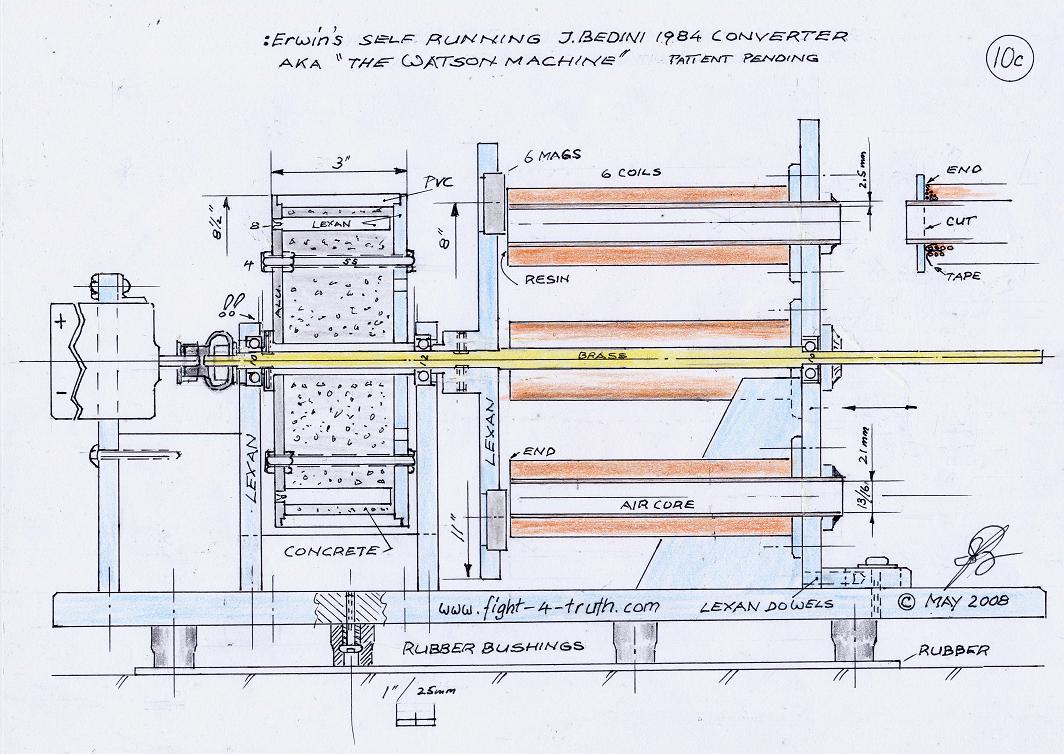
For my flywheel I am using an 8" (8-1/2" OD/216 mm) water main PVC pipe 3" or 76mm long. 3-1/2 or 89mm Alu. bushing over the 1/2"/13mm shaft with a 1" = 25.38mm collar for the set screws, on the other end a small step for the Lexan plate. Make sure this bushing fits between the two 12mm bearings on the inner race only and bore it out with a boring bar for a slide fit. If you use 1/2" brass shafting you must machine it down to12mm for the bearing to slide along it with a little step at the shoulder for a good fit. Use a little Permatex Locktite if you think the race will turn on the shaft on the first one. On the stator side I used a 10 mm bearing On the collar side I used 1/4" x 8 1/2" OD stepped aluminum which I shrank onto the Alu bushing and on the magnet side a 1/8th (not shown on the drawing) stepped 1/2"LEXAN cover, is for safety. File two flat spots onto the 3-1/2" Alu. hub-bushing, the same to all the plastic dowels, making sure nothing turns in the concrete.
I used 6, better is 8 plastic dowels 5/8' or 16mm Dia. are for lead weights balancing purposes while four SS bolts (ready rod) holding it all together; Spent much time balancing the wheel and it paid off. If you center drill the plastic rods which are fitted with step into holes on the alu. disc you can later drill them out according to weight size of the threaded lead weight which you established by tacking weights to the OD of the fly wheel until balanced. I just used scraps of steel and mg scale, cut and threaded the lead rods with slot on one end and a little longer as needed for trimming later. I actually used birch wood dowels but do not recommend them since the threads do not cut into it worth a hoot. 1/2" Lexan cut into strips and machined makes good dowels, by the way. (Loose fit make room for glue). On dowels for the flywheel leave a little of the flat part as you machine it down for anchoring purposes.
For the mass I poured a rich (two parts cement) concrete mix using coarse sand and 1/4"/ 6mm screened gravel. You need to drill at least four 1/4" holes in the Lexan cover for the water and excess soup to escape after you squeeze it all together with the four rods and clamps, use plastic mallet and work it real good. The reason I used concrete it being neutral to flux currents, cheep and heavy, with total weight of 6.5kg. Standard concrete mix is one part Portland cement, three parts sand, four parts gravel and 5 gallons of water per 94 pound sack. Off the cuff, the water content in the mix is good if it sticks to the tool, like stiff dough. About the mix among other things see Index No. 8 Back to Basics.
I used 1/2" Lexan for the magnet rotor disc. Lade out the 11", then the 8" circle with the 6 center marks and 1-1/2 circles. Used the band saw to accurately cut along the circular OD line, then drilled a 1" bore 1/8 deep with a spade bit, preparing the rotor for the glued up hub assembly.
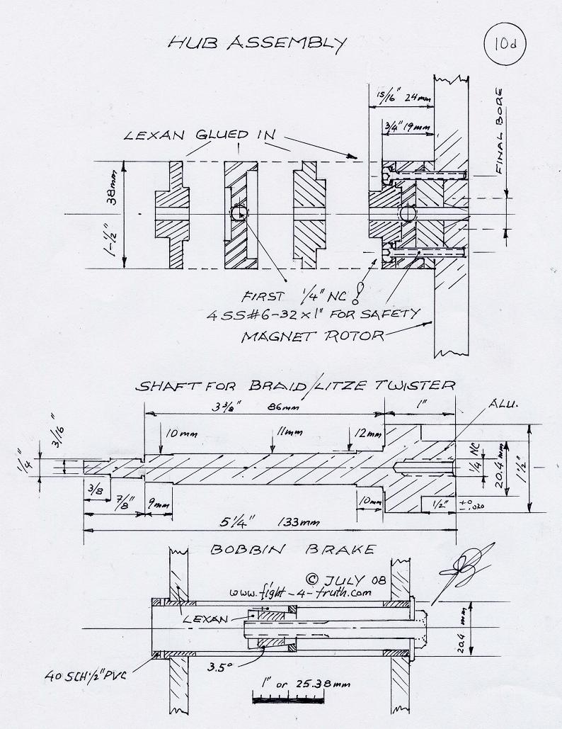
For the hub I cut three 1/2" Lexan disks 1 -1/2" OD which I machine on the lathe with individual steps with loose fit for the glue, glued them all together let set over night under "light" pressure and cut the threads for the set screw before I glued the hub assembly into the rotor center with 1/4" bore and held it all together with four #6-32x1" SS screws for safety, then finish the 1/4" bore. For the ones interested exactly in how I worked the hub see the drawing below. The Litze or braid-winder shaft and bobbin brake will also be on that drawing. The bobbin brake is not necessary for # 26AWG.
I used 2 set screws in the hub. Make sure to file a flat spot onto the shaft for each set screw. Also make sure not to over tighten screws or pressure in the vice otherwise the Lexan will answer you with cracks all around the work peace or bolt heads. Bore rotor out to fit the shaft, then use a mandrel for machining the OD of the rotor on the drill press if your lathe is to small, which is the reason for preparing the OD of the magnet rotor as precize as possible.
On the six holes use a 1" spade bit (must run true) to start each bore then use the rough boring bar for the last 1/2 inch and adjust it in 2.5mm increments focusing on the 1-1/2 circles as you machine out the bore except the last setting for a 1.5mm step on the 6 - 1 1/2 holes for the magnets to protrude with press fit of 0.003". I used the screw vice to press them in, you must feel a slight pressure when you tighten the vice making sure you can't push them back out by hand. Loose is no good and too tight is to risky. Machine a test hole until satisfied, then use that specific boring bar for all six holes.
Do not forget to mark all the magnets with the "N" north towards the stator plate.
Do not forget to balance the rotor perfectly. Drill holes close to the 11" OD where needed and glue in lead shot.
Accuracy in all your work done is of utmost importance if you want things to work properly in this machine, no room for sloppiness!
The temporary 12 V permanent magnet DC motor you see in the picture below is off my 1980 VW Rabbit radiator fan. It runs at 3500RPM consuming 24A at start up and 4.5 A at top speed. I start it up on one of my garden tractor batteries, once the rpm is up I switch it over to one of my computer power switching supplies for the time being for the good of the battery. It is a bad habit to draw current off a battery and letting it sit without recharging it! I won't use the self-runner commutator until I have the proper output on the energizer coils.
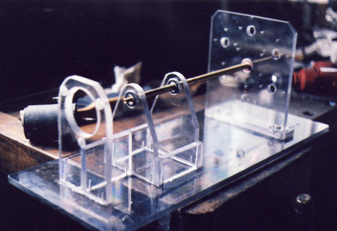
Had to build two skids for the base, (not shown in my drawing below) too much flex in the Lexan, hard on the brass shaft. Rubber on rubber works good to kill vibrations. I found some rubber bushings from my monitor and printer salvage parts 5/8 by 3/4 high and 3/16th bore (drill a hole in hard rubber works also). Machined a little Lexan bushing for the screw shaft halve up the rubber bushing screwing it to the two birch skids underneath the Lexan plate. Further I cut two strips off of a 5mm inner tube (from logging skidder) and set the whole machine on it, which held the machine in place.
For the motor shaft interconnection I used a small flexible coupling (Princess Auto) with 5/16"/ 7.5mm bore OD 1-5/64"/ 29mm with spider overall 1-23/32"/ 33mm : L050 series, which is designed for low hp application. The item is sold as two couplings with a solid "hard" rubber spider. Better you use a softer flex coupling like I show on the drawing below..
Setup is quite touchy; it will wine and bind if it isn't just lined up right, hence the Lexan motor mounting plate must be adjustable!
On the 1/2" stator plate I changed the position of the coils making room for a plate support.
The wiring and switching of the machine is illustrated in my drawing No. 10b Bedini-Tesla-Gray Home-Power jpg. INDEX xxx in Schematics Illustrated
Build a safety shield around the flywheel and magnet rotor if you run it over 1800 rpm!
Image 11
The Lexan mounting side of the coil is held in place with two #6 x 32 crews and a small Lexan disc glued to the end of the core paper once the coils are mounted permanently.
The 20.4mm coil core, pipe size and length works perfect for the four, resp.six bobbins I'm using on my winding machine. I can expand the machine to 12 or 18 lize if need be.
The core is the full length and the Lexan end-disk is just tacked onto the paper laminate which is resting against the lathe chuck squeezing the paper to the core pipe until the copper layers are finished, the end-disk removed and cut to length as you can see in the inset. I used little plastic tape strips to keep the end turns in place. A good safety resin coat protects the copper from the magnets.
The 136 V of the last quad-filar coil which I mentioned below I haven't surpassed yet.
I am aware that I may be trying to hard to get that individual coil voltage up. It all will depend onto the sharp gradient caused by the commutator, brush adjustments and coil setup to get the voltage where I need it. I have many unanswered questions though. Well, I will just tackle them one at a time.
This last two drawings are premature, I put them up for your sake. I know that I will have to make changes, but in the mean while you have something to look at and stimulate your own thinking. See also INDEX xxx Bedini-Tesla-Gray home power in my Schematics pages
Image 11c (photo is comming)
Image 11d
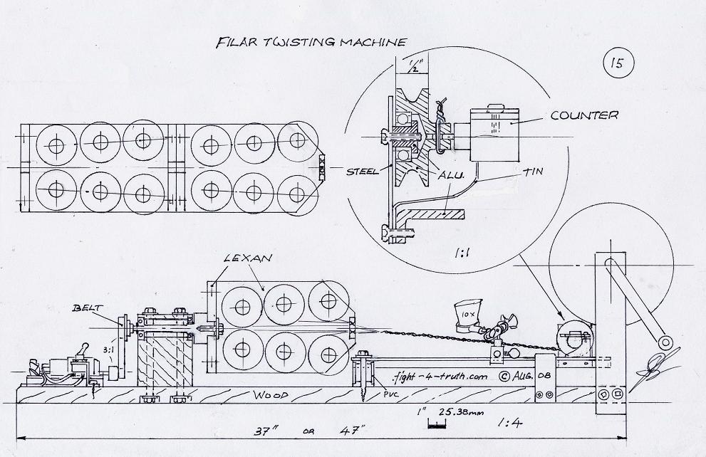
Driving motor, belt and 2 gears at 2.8:1 ratio, switch, shaft and support, 2 bearings, 2 Lexan housings of 6coils each, PVC bearing guides, 6coil brakes, eyelet and support, magnifier glass, wheel counter G14353, guide arm with slide bracket and a 1" x 6" or 15.2cm x 36" or 91.4 cm birch board for the base to support the machine. Add an other 21cm if you are planing to use 12 coils.
By the way, for the ones not used to reading cm just drop the fraction period and call it mm ---->15.2cm = 152mm.
Since I was all busy winding long coil cores, I used the same pipe and core length to cut 4 bobbin cores 2 -7/8" or 72.5 mm in length and built the twisting machine around those bobbins. In the back of my mind is that 12 filar Monopole coil, hence I designed it accordingly. It is easy to fill small bobbins with copper wire on the lathe. All we have to do is use a wheel and counter to measure the amount of wire going onto the bobbin for the individual coils being used in order to prevent soldering connections or ending up with long left over useless pigtails.
You must take great care gluing the bobbin flanges onto the paper roll, use big bead on the inside. If you don't, the pressure of the copper wire will push the LEXAN disks off the ends with binding results within the housing and a broken strand.
The bobbin cage:
The bearing-plate with center bore of 20.4mm is 1/2" Lexan 2-7/8" by 5-3/8" or 86 mm with 1/4" x 5-3/8" x 8-1/4" or 21cm side walls with a 1" x 2-7/8" end-plate and 6 or 12 - 1/8th holes drilled on a 12mm circle. For clearance of the wires the six 20.4 bores in the side walls have a trapeze shape centerline starting at 1-3/4" or 45 mm from the edge of 72mm and 86 mm at 65 mm apart each with a total trapeze hight of 130 mm. The side plates are bolted to the bearing- and end-plate. The bearing-plate is tightened to the shaft with a fender washer and 1/4 NC bolt.
The 3-3/8th measurement on the shaft you can easily change for a 2x4 which is 3-1/2" if you can't find a piece of birch to size. If you change the dimensions of the shaft, make sure you have enough meat on the thick end because 12 or more bobbins are quite heavy.
I'm driving the shaft by a rheostat or 24VDC/5VDC wall outlet power supply with a small 120VAC PM motor over a belt and pulley which I robbed out of a carpet cleaning power brush. There is also a good low rpm PMDC motor with much torque available from Apex Electronics in CA, U.S.A:
0.5 AMP - 30V specialty motor $10.- each P/N # MTR22-W. (It is a servo motor).
http://www.apexelectronic.com/
The twisting magnet wire is guided through a wheel counter with magnifier glass and via a 1/8th tapered angle guide bar/arm onto my 7" bobbin on the hand cranked coil winder at the end of the board, which is bolted to the edge with two #6 x 72 mm wood screws. The bobbin is weighed on my balance with an equal counter weight of lead peaces to equalize the weight of my long coil as I'm winding copper onto the 7" bobbin to figure out my equal footage. The tapered bar/arm is L shaped with a wooden handle which handle is not needed. It is easier to just hold the arm near the slide braked and guide it back and forth filling the 7" bobbin.
See the drawing... The 22V out of the 24VDC wall mart gives me just the right RPM, although the motor a little weak, is twisting the wire, without heating up. For #18AWG wire I will likely have to raise the RPM and change the ratio or use the bigger MTR22-W motor. It is working just fine. This wire is wound equally and tight without having to apply the bobbin brakes. Turning the crank looking at the counter as the tenth digit is switching in approx. 1.2 sec. giving me 5 twists per inch. Each bobbin must have the same friction tension and be shimmed sideways within the housing to have a smooth and balanced rotation, which is not hard to do.
Of course there is more ways to this operation. If you are planning to build many coils then you don't mind to scale up and use the 6" reels from the factory winding the twisted wire directly onto the final coil via the counter for proper footage.
Image SS My space ship
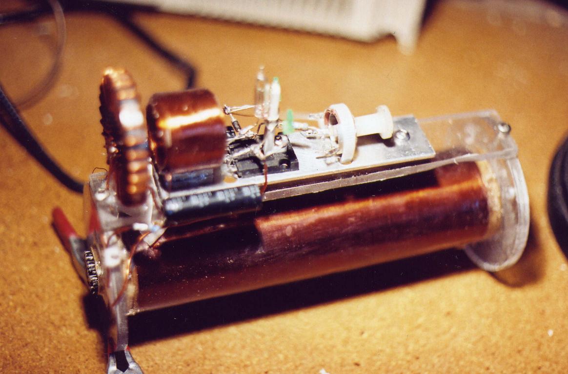
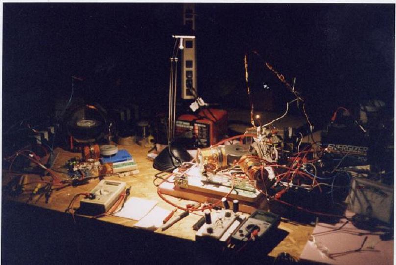
I mounted it properly with ground and all the right HV cables onto my "simple monopole machine" test bead and to my uttermost joy it worked right off the bat. The two LED's where showing me when the magnets where approaching and leaving the coil core, meaning that the trigger coil was working (afterthought because I got ahead of myself) and was triggering the MJL21194 transistor on and off. A great accomplishment for a guy like me! Figuring out the cap is next.
Once I get the next film developed I will add the photo to all the details. They are details of small potential progress, but never the less we must crawl before we can walk, which gives us time to organize, become familiar and get use to HV safety.
SG2 Simple Monopole Machine Dada, charging an old 850CCA auto battery while driving a generating coil.
One master one slave each 10 BD 243C transistors paralleled in a piggyback setup (I do not recommend this practice for charging batts., I used what I had too much of) 6-filer, 5- #18 and 1- #23 150' old coils (better would be 300 feet 16 strands). Coils size is 3 -1/2 x 3 -1/2 with 1" tie wire-core. 12 - 100 µF 330V photo caps, 16RIA18, 4" x 4" Alu-rotor with 1x1x4" ceramic swallow-tailed magnets. Frequency is around 332Hz ( 332 x 4 magnets = 1328 rpm) with coil output at 15.6 VAC, FWBR at 14.1VAC, SCR at 15.2 /19.30DCV no zener, primary in at 24V/2.2A while charging at 1.1A (current is to high due to piggyback setup) , trigger total resistance set between 470 to 510Ω. At this current drive, this particular battery being placed in a charge/discharge cycle is being charged from 12.20V to 16V in 20 min.
The generating coil (my space ship) is just a standard spark coil and not a Bedini! I had to start somewhere with the benefit now of knowing a little more!!! I'll spend some more time with it at a later date.
These are the numbers I'm starting out with before I am changing things!
Primary coil #18 AWG magnetic wire of 296 turns in 2 layers at 1.0Ω and output at 122Hz is 3.4VAC
Secondary #30AWG in 15 layers at 330Ω at the spark gap and output of 104VAC
Trigger coil #26AWG at approx. 300turns in 7 layers with a total resistance set at 480Ω and 3VAC operating from:
Base/emitter at 0.3DC (0.6VAC), Base/collector 0.7 DC and 0.7/0VAC, collector/emitter at 1.16DC and 0.17/0Vac
Coil strands soldered in series example.
I have this little try filer coil of twisted magnetic wires #23 and one #26AWG with a half inch tie wire core sitting around, which I built at the beginning of my venture. It came in handy for four little generating tests holding it in front of the 4" monopole rotor running at 332Hz. Keep the smaller wire size in mind, it could possibly have an effect on the volt-ratio. I just used it for confirmation of my thoughts.
1. The wire ends twisted up, its resistance measured 1.9 Ω and it generated 3VAC.
2. The three wires hooked in series at each end, like an S, it measured 6.2 Ω and generated 3.3VAC.
3. The number 1 wire on the other end of the coil side hooked to number 2 wire on the polarized side,The number 2 wire on the other end of the coil side hooked to number 3 wire on the polarized side, which left me with polarized number 1 wire and end wire 3 open, where it produced 11 VAC.
4. Air cored, after having removed the tie wires, the coil generated 5 VAC.
Now the question is" what is better; Neodymium mags with air cored (used in high voltage and high frequency applications) coils which and therefore no cogging of the magnets caused by the magnetic core and less voltage per turn, resulting in highest RPM and least primary consumption, or Neo's with magnetic sand core coils and lesser rpm and result with more conductor pressure and more driving demand? How much voltage do I need to shock the RE (radiant energy) into existence in this machine? John Bedini's impulse technology comes to mind.
Image 12 Enhanced conductors
Here are a couple of lines out of Nikola Tesla’s Patent 512’340 Jan 9th 1894 regarding the pancake coil:
…..If now as shown in Fig.2 a conductor B be wound
parallel
with the conductor A and insulated from it, and the end of A be
connected with
the starting point of B, the aggregate length of the two conductors
being such
that the assumed number of convolutions or turns is the same, viz., one
thousand, then the potential difference between any two adjacent points
in A
and B will be 50V, and as the capacity effect is proportionate to the
square of
this difference, the energy stored in the coil as a hole will now be
two hundred
and fifty thousand as great. Following out this principle, I may wind
any given
coil either in whole or in parts, not only in the specific manner
herein
illustrated, but in a great variety of ways…..
Here are a couple of lines out of Harry E. Perrigo's
Patent 78'719 Dec. 31st 1925 regarding inductors coupled in series from
polarized north to south.
"Excitation winding wound to produce magnetic lines of force from
polarized north to south in progressive degrees of electric induction."
...and don't you ever believe for one second that Harry E. Perrigo was
a fraud.....as an inventor he was brilliant!! By just looking at those
two
thugs faces flanking him by his car, the right answer will dawn on you.
http://www.rexresearch.com/perrigo/perrig.htm
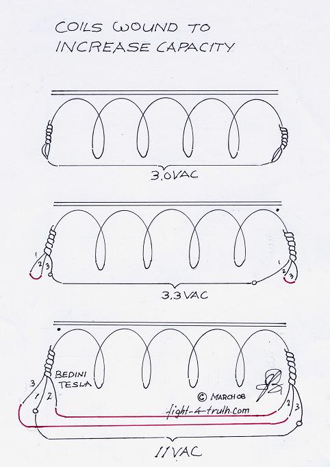
In filling that capacitor in those nanoseconds the magneto is charging the primary and the cap is dumping the accumulated voltage back into the primary at the magnetic field collapse to create that shock we need to acquire those aether waves . If I can't get this coil to work right quick, I will, with the new knowledge gain, just build a better one anyway. I will keep concentrating on John Bedini's latest remarks in his groups. I know I will get some benefit out of it as usual.
It doesn't really matter how accurate my theory is, what matters is that I will make it work with the Savior's help through the inner feeling, you might call it 6th sense, I call it guidance towards which book to reed, which voice to listen to and which direction I should take my steps. Talk alone is cheap, positive action is what is the most important thing in life.
The twist: Posted: 10/25/08
I wound a quad-filar air cored #23AWG 24 layers 2" by 9-1/2" long 140Ω
Never mind the twist, the new coil 146Ω I wound with the four wire twisted same size and weight in copper, except 1/4" bigger in diameter because of the air gaps in the twist, only put out 110V, which tells me John Bedini is using the twisted wire mainly for convenience and also to make it easier for the replicator. I'll think twice before I'll twist the next quad-filar coil, I will save an operation and gain room on the bobbin by using the 4 groove sheave. The voltage gain in the 1:1 coil for battery charging in none twisted filar wire will have to be varified.
For the ones that want to use the 4 or 6 groove sheave; I started counter clock wise (normal forward) on the lathe taping the ends up the disk to the chuck (polarized side of the coil) and carefully placing the strands on the core side by side slowly turning the chuck by hand for about three turns continually pressing my finger slightly against the wires on the bottom of the spool guiding the strands from the sheave onto the core of the spool in parallel while making sure everything stays that way while running the lathe in low gear slowly. The moment a wire gets crossed I stop the lathe and temporarily masking tape the copper on the spool stopping it from unwinding. The winding onto the core is fast with the finger pointing the right way...where as the trouble occurs at the ends where I have to guide the strands to the end disk until touching and then back again in nice orderly fashion without any wires crossing the others or causing gaps...It takes a little getting used to; it is definitely doable though. If a gap occurs which can't be changed I fill it with fast glue.
Well...the twisting machine will come in handy for the 12 filar coil since I don't think of attempting to use a 12 groove sheave to do the task.
Now the next question is, will the generator coil hooked up in Tesla fashion produce more HV in a sharp gradient setup as the same amount of just simple straight wire? According to Tesla there should be a great gain at least through a spark gap.
| INDEX 1. Casting a "Yogurt" Rotor , 2. Rotor mold, 2a.Commutator mold, 3. Magnets, 4. Supper Glue, 5. Balancing, 6. How to build coil bobbins, 7. Length, size of wire and cables, 8. Twisting the copper wire, 9. Wire winder, 10. Filling the spools, 11. Right hand rule, 12. Coil cores, 13. Energizer / rotor Base, 14. Bearing assembly, 14a Oiling lower bearing, 15. Birch wood, 16. Mount coils, 17. SSG John Bedini circuit, 18. Transistors, |
|
The URL of this page:
http://www.fight-4-truth.com/Work%20Shop.html
