Crossflow turbines
There are two distinct turbine designs, one for low, the other for high pressure application. Contrary to some individuals who claim that Crossflow wheels are impulse wheels, my crossflow blades derive their power by reaction not impulse (impact). My turbine blades are designed to create lift, like an airplane wing, thus the water velocity flowing from the leading edge over and under to the trailing edge causing a pressure differential in the upper (camber) and lower (chord) lift surfaces of the hydro blade, thereby creating a lifting reaction the result is much extra torque to the shaft. As evidence to my statement check out my Prony brake test.
If only the lack of experience in electricity is holding you from jumping at it with "all four", then just read through my work shop and schematics illustrated and start from scratch. Study the novel principle of extracting Radiant Energy or cold electricity from the air by creating a sharp gradient and shocking the RE into existence through DC pulsers or transistors for your own use. By the time you have read all my Bedini pages and have practiced some of the switching procedures, you'll be ready to build your own electrical energy generator, I mean creating your own power. :)
I do not belief in the term of free energy since no gadget is falling in your lap for free, you'll always have to sweat and reach into your pocket, be it by building it your self with the needed shop equipment or farming it out, unless you try to buy it for big bucks and get taken*$%^.
Keep your formulas in your pocket and listen to my practical reality talk. The 26" 16 blade low pressure wheel 12" wide, a 9-1/2 chord, 3/4 draft and (D) opening of 1-3/4" on a, three foot head would get you between 4 and 10 Ampere through a one by twelve foot culvert 1/3d volume of water. Even though the 12" intake of a 10 foot pipe is fully submersed (1 ft below the surface). The outlet volume of the creek can be controlled seldom more than 35% of its diameter, except in runoff on higher water volume when you could let the 12" penstock rip full force to which the site was not designed for though; shut off, flow/vacuum and water level is therefore controlled with a peace of 3/4 plywood at the intake of the penstock. You can't have air in the penstock if you want to make use of the full head pressure...and that is not always possible!! In the dry season for instance.
In any case, I haven't seen an average of 7amp output in any table or performance sheet on a 3 foot head with that small amount of water, in fact I haven't been able to find any Data below a 6' head of water.
In a low pressure dam setup you use sometimes every drop of the creek water, whereas with a high pressure dam and full headrace with a steady penstock pressure, all is totally different, in which only a small percentage of the creek water is being used. For low pressure without a gate one can design a smaller pipe and run it full flow, except when the water level in the dam drops to a certain point where the intake will suck in air, hence you run out of vacuum/siphon effect and torque, then the pipe is to small because of the water/air or even ice mixture. Yup, I'm not kidding, when winter weather conditions are accordingly, the whole creek is full of ice crystals mixed in with the water just like a freeze drink.
The output depends on the volume of rain, snow fall or frost/ice, water volume of the creek and level of the dam, which is the reason for the big diameter penstock and wide margin of the power performance.
The above low pressure description is my turbine and it is running to this day and the Frenchmen who is running and enjoying the "free electricity" !!*♫♪¿#^ is busy doing it.
By the way, if the so called government is trying to charge you for the use of the creek water, then ask them to prove to you that their laws are written in the truth and make sure they sign all their correspondence. They won't be able to oblige because they are all guilty of mail fraud using the fiction verb language . Click for my Facts page and paragraph 3,7 and 12 to 18.
The high pressure spinner is usually from 6" to 12" in diameter pending on the pen stock size and the same width as the DIA, with many narrow curved blades, short chord line type, lets say 1/4 cuts of 70mm (wing chord) out of a 4" pipe much like a squirrel cage runner of an air fan. The entry angle is the same as the exit angle in relation to the blade (wing) chord. The blade width should be 46% of the radius. The runner has a stub shaft to clear the path of the water flow across the whole diameter of the wheel supplying torque twice by hitting the first blade flowing in and the opposite blade on the way out at about 30%. For most torque and efficiency the water stream must hit the trailing edges of the exit blades on the correct aoa, which can only occur by the main stream traveling close through the center of the wheel not the edge.
These wheels spin very fast and are quite forgiving allowing smaller debris controlled by a 3/4" to 1" mesh screen to flow through them without any problem. They are also easily fabricated by trade's men, meaning anyone who has the ability to build the real thing from a drawing. Torque can be altered by an adjustable fin or guide vane (air foil) inside the water stream, which is not shown on the turbine below except partially on the drawing.
The nozzle design and guide vanes play a major roll in medium and high pressure crossflow turbines for maximum torque. It totally differs of the low pressure narrow slot design. It should be designed in such away that the main water stream must flow through the center of the runner for best entry angle through the second blades and exite of same, which can only be accomplished by using up a big procentage of the circumverence of the runner. The nozzle width should be 36% or 130º of 360º with an even water velocity entry angle across the whole nozzle, across the radius side, not the length along the runner. With other words the stream of water should hit at once as many blaids of the runner at the same time as possible without sacrificing lift/stalling. A wing stall occurs when you loose lift and the lift is created of course by the camber relative the chord line and flow angle of the adjustable guide vane/s through the proper entry aoa. To much aoa will be the cause of turbulence over the blade/camber and loss of lift. Two adjustable guide vanes give more advantage to flow control to the individual blades even with one shut down although cosing some turbulence while the other is in full flow position, whereas with the one vane the correct aoa to every blade is impossible without any sacrifice also it is either on or off because the moment you start closing it, all the aoa's to the blades become out of whack. The flow angle is adjustable from shut off to full flow. In the full flow position the guide vane/s direct the waterstream in the center region of the nozzle into the proper aoa of every individual runner blade.
The low pressure wheels are about 24" in diameter at 70 to 100 RPM relative to the load size, which is slow **, with a through shaft design with its blades being quite different in shape compared to a high pressure blade. A 30" x 10" runner with a 10" blade chord length and 18 blades would produce more torque than the 26" below because of the radius lever, longer blade chord and extra blades, but you'd sacrifice rpm, of coarse relative to the same water volume flowing through (D). I would say that (D) square should be 10% smaller than your average penstock water square making it the No. 1 factor for your design. The water velocity increases as it is forced by back pressure through the nozzle (D) slot. Since the water velocity is comparative slow to high pressure, 95% of the energy is used up flowing through the first blade; hence the design of the blade is quite crucial. The water moves across the blade surfaces (over and under) in slow motion in relation to a high pressure wheel and at the trailing edge of the blade near all energy is spent. There is the possibility for the presence of a little more lift as the current flows through the second blade. The idea is to get the maximum lift for torque out of the first blade by using the proper wing root/camber design and angle of attack (aoa) (or water incidence angle) meaning the angle relative to the chord line of the blade (wing) and entry line, thus it must be of the long chord line type. If one would fabricate the blade with a flat instead cambered chord which would be much work, although the lift would likely be that much better. The entry angle is not the same as the exit angle, the exit is quite flat in relation to the blade (wing) chord and entry. The water stream also exits on the same half of the runner where it enters bypassing the shaft.
A wing under water acts very direct but similar to a wing in the air.
The ratio** Because of the water velocity being slow the runner rpm will be low therefor we must up the rpm to create electricity, which is the reason we want the best hydro torque to the shaft we can muster. The sprocket gear pulley ratio should be 1:10 and up. The more rpm you want the more torque you need and we want as much rpm as possible to run the alternator. The trick is to choose an electricity producer with little or no torque, which usually has a high rpm envelope.
The reason for the sprocket and chain would be the runoff season, which is driving the creek water level up sometimes close to the turbine shaft. A remedy is extending the turbine housing with a seperate drive compartment to keep the water out.
Low pressure nozzles can get tricky if not impossible to clean out if you don't built an access lid close to the nozzle adjustment. A Plexiglas lid is handy to keep an eye on the water stream. At one time, while I was changing both screens, a submersed 2"stick skipped by ...clunk........ **#¿ǿ΅↓^ as it was jamming my runner.
The nozzle adjustment blade is welded to a short arm reaching up to the control lever shaft inside a little dome welded to the penstock. The shaft is sealed with standard lip seals or O-rings through the dome; same with the rod moving the adjustment blade, a lip seal ring is threaded into a welded nipple into the penstock.
Don't use a concrete base for the nozzle entry, it is too complicated to build air tight. I had a u-frame over top of it which was bolted to its sides for removal. The chunk of concrete got eliminated when I built the housing. I ended up fabricating the penstock from 16 and 20 gauge sheet metal which is 1/16th -1/32nd or 1.6mm-0.8mm and 1/8th - 3.2mm for the flanges.
Blade angles are quite simple to apply once you know what to look for. The blade entry of the one side of the runner is a continuous smooth s-curve to the opposite blade and exit no matter what size of radius you are using. No kinks can occur. Starting at the center of the runner diameter moving outward on the center line to the beginning of the blade radius line, you must have a smooth transition. Think of the line as unwinding a wire or rope off a spule, same Idea, transition from the radius onto the centerline must be a smooth transition which is at 90º to the center of the rad. In this manner the blade angle at the OD of the spinner is correct if you use a1/4 section (70mm) of a 4" pipe for a 12" runner. The water velocity angle or aoa has to be 16º from the blade camber line at the leading edge of the blade, see drawing below
Laying out your turbine blade on paper. Start with a horizontal center line of the wheel, off 90º from that, make a center mark at 2", draw the partial circle from your 90º corner and add a 70mm long chord line from the same corner, change the compass to 6" radius, set the pencil end on the leading edge of the blade and the pin end onto the horizontal line, then draw the circle of the wheel. Voila there you have the position and proper angle of the blade for the high pressure runner.
Look at my 8" Crossflow drawing where you will see my blade layout. It is not very accurate because I could not see it well on that little 8-1/2 x 11 format. For the blade width I drew a line at approximately 46% of the 4" radius which is in reality 1-13/16" or 46mm wherefrom I added the 45º diagonal following with a square off the crossing point of the 4" or 101mm radius and diagonal which gave me the 1-1/2" or 38mm rad. or 3" / 76mm diameter pipe/tubing to be cut for the runner blades. If the rad. dos not work out to a standard pipe diameter for you, then just size the square (blade width) slightly up or down 'till you have it.
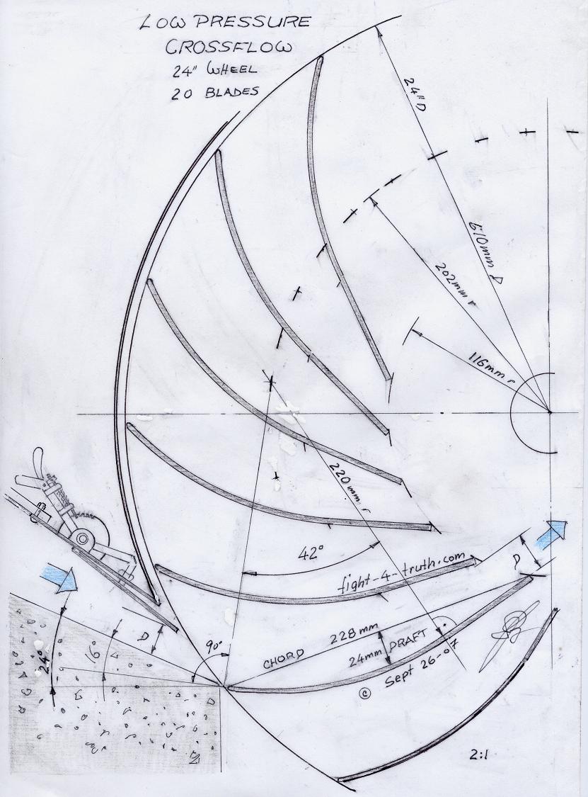
The low pressure is slightly different. Draw the center line of the wheel in the middle of the page, then an other parallel line 3-3/4 below in the left corner about 3-1/2" long, then draw a line back at 24º with the help of the protractor which is the angle of your penstock, water flow line and aoa relative to the flow of the water to the blade. Draw a line 16º below the penstock angle line which will give you the blade camber, then draw a line 90º to that and with the compass draw the 220mm or 8-5/8 blade radius off that line, for the 42º pie shape . At the bottom of that line at 90º you would be extending the blade camber with a straight line 76mm or 3" long which gets you to the blade trailing edge from which you draw the chord line to the leading edge of the blade. You should have a draft of 24mm or 15/16th. Now that gives you the position and proper angle of the blade for the low pressure runner.
The overall size of the blade and width of the low pressure runner is found by the blade surface in square-inches/cm being also the same as the square inch section of the pen stock DIA or square surface once you established the chord width of the runner blade (wing air foil), then add 2" / 50cm to the length of the blade which gives you the total length of the runner. The inlet nozzle should be adjustable according to the flow you have, between 1-1/2 and 4" slot on the whole with. Through practical application I found my theory most revealing at construction of same. Also I had pored the bottom of the nozzle with concrete (use only 16 to18 gauge sheet metal and 3/16th for flanges) making it difficult setting the aoa (had no blue print, started from scratch), thus the maximum torque and aoa I found by direct application of trial and error by welding two round rods onto the trailing edge of the blades and holes are drilled into the sidewalls of the runner. By installing the blades in this fashion they are then tacked with the welder on the very outside edge in order to grind the tacks off easily for each adjustment. The best torque reach is found by installing a torque instrument like a Prony Brake onto the shaft and by hanging weights onto the end of a 1 meter bar and slowly tighten the bar letting it slow down about 50% or best torque reach, then with the same weight adjust the blades back and forth or from 0º to 16º aoa in half inch increments until it speeds up on that same weight setting. When I was done I noticed that the blade-exit-line pointed some inches past the center of the runner making sense because the now unrestricted flow was missing the 2" shaft pipe which was in the center path at first. I also knew that the Banky turbine's water path did not flow through the center of the wheel either.
The low pressure blade for a 1 foot pen stock should have a blade measurement of 9" ore 22.8cm long by 12-3/8" or 31.4cm wide. Measuring from the trailing edge 3" or 7.6cm on the brake starting to bend the radius at 3/4" or 1.9cm increments until a draft is achieved between 7/8 to 1" or 22 and 25mm (8-5/8 or 220mm radius. The chord width of the blade is 75% (228r : 305r x 100) of the runner's radius compared to 46% (70r :152r x 100)of a high pressure blade. The more camber and longer the chord the more lift the blade will produce. A similar comparison is an ultralight aircraft to a high speed glider wing. The more water volume through the penstock you have the shorter you will design the chord width of the blade or number of blades enhancing flow between the trailing edges (D) of the blades. In my drawing below I just guessed the blade gap on the circumference; you'll have to lay them out properly with the compass.
The Prony brake I built with two birch rods/laths with the main bar as one meter long and the other 100mm long with two screws, washers and wing nuts with a 1/4" spacer between the rods, then drill through the center of the spacer for the size of the shaft and remove the spacer and mount the instrument onto the spinner shaft.
Torque test: With a three foot head you must undershoot the runner for lack of room. In my testing days just for curiosity and wanting to prove to myself my theory I tacked straight blades onto the runner sides with a test weight of a few ounces on the torque instrument or Prony brake before the runner stopped dead as a result; then instead the flat blades I tacked the wing shaped blades onto the runner walls and directed the flow onto the leading edges of the blades with the result being able to add a 5 Kg weight onto the 1m end of the torque brake bar right off the bat, where the runner slowed down some only. At 8 Kg it was down to 50% and staid there. This numbers might not be 100% accurate since it is quite some time ago when I tested the wheel for maximum torque and never having it written down. I think you will understand that you get much more torque to the shaft by directing the water flow through the leading and trailing edge of the blade (over and under the wing/blade chord) instead of the paddle wheel type direct impact or bucket design.
The turbine size you'll calculate once you choose your size of penstock which will give you the diameter of the runner you want to build and by using the thickness of the nozzle across the diameter of the runner as your basic number to calculate the width of the runner ending up with same nozzle cubic volume as the penstock water volume less 10%, then add 2"/50cm to the width giving the runner side clearance from the nozzle stream.
The
Draft tube is
used for more efficiency if you have the head to play with. In stead of
spilling the tail water onto the tailrace a conical tube is installed, slowing
down the water to the normal velocity head, creating a vacuum at
the
discharge end of the runner by guiding the tail velocity into the small
end
of the cone enhancing the head, meaning additional torque. The total
cone angle
should not exceed 10º to keep the water
adhere to its sides.
The Load cotroll governor's load is
controlled at the
alternator side not
on the turbine. Usually a hot water element is used for the dump
purpose.
Building
this
little dam
is not as simple as it seams because you have to consider the big water
volume and ripping powers of a spring runoff. You have to make a good
footing and use
re-bar (at 1ft square). Place 3/8th steel especially on every critical
stress
position like key grooves and sluice corners tied to the footing 3/4"
from the edge. The re-bar has to be placed close to the forms, not in
the middle of the wall, but along the wall down stream at 3/4" along
the framing
use 3/4" chairs or little blocks, that is the position where the crack
will
occur before the dam brakes. Set
big boulders in front of the footing (With backhoe) or tie them up with
concrete (If you can't dig
down to solid ground or silt). For the forming I used 1x4 to 1x8 boards
twisting tie wire around nails for tie bars in between the boards with
6" wood spacers which I gradually removed at the poring stage, make
sure you vibrate all the air out of the concrete real good with the
hammer if you have no vibrator. On a
three foot high dam a 6" width is
plenty. The dam will have to reach 3 feet on both sides into the creek
embankment. The sluice /flood gates consists of usually 3 boards of
2x10x36" steel channel screwed to bottom board. The sluice openings
have
to be big enough to handle the full runoff volume. Stay as far away from the
penstock inlet as possible with the gates. You have to be able to
move those boards up the key slots
previously cast into the concrete in increments at runoff whence you cut the plastic.
I actually got away with the odd time duct-taping new plastic to the **existing
one
to seal the dam again for the next season.
Build a separate little overflow for a fish pool ladder with rocks and
cement along the embankment up to the top of the dam.
**Once the dam is finished and you don't want to get caught with 30% of
the creek seeping away underground then remove all rocks, creek bed
gravel and 6" of silt out of the dam site for 10 feet where you dig a ditch (as
deep as you have to) to start the plastic liner and
line the whole creek bed with a 6 mil plastic, no seams and draw it up
the sides of the bed and
to the top of the dam and weight it down with boards and rocks. If you
pored the footing onto clay or bedrock then you do not need the plastic
of course. If you
are a wizard you had casted along the top of the dam a 1x2 board to
tack
the plastic onto it every year. Replace all the gravel and rocks into
the creek bed exactly the way it was!!!*#??^
Once you have to start opening the
sluice at the bottom board it will then pay off having the screens
close to the current at the end of the cat walk, there will be no settling of debris
or gravel as the water volume increases cosing a
bottom current also it will be very practical having placed a 6"x10' steel plate
or old snow plow in front below and up stream of the penstock intake,
forcing all the
rolling gravel bypassing the 1-1/2" mesh intake screens in the spring, making sure the screen mesh is
no bigger then the blade gap (D). If you have'em much smaller
they
will plug up to fast. Use two screens one stationary the other
removable
for cleaning otherwise you are asking for trouble. As the creek is
building... up comes the bottom board by the help of a steel bar, if
you wait to long the pressure will be to great and you are not going to
move that bottom board!
The other day I visited a fellow’s micro hydro site.
His piping was 128 feet long at 3” DIA. He had 28 feet of hydro head and 45gal/min flow rate on the site a couple of boards two feet deep backed up water and some of the water was overflowing. The gully was 6 feet at the bottom 20 feet on top and ten feet high where it eased pack. Are you thinking what I’m thinking?
Temporary top volume is the answer. The bigger the dam the bigger the body of water the more head and power you can develop, even if it is only for a given duration. You need an electrically controlled main valve in front of your turbine which opens and closes the line from its maximum diameter to calculated given maximum flow rate where the water level at the dam stays constant or rises some. With other words, at times of highest demand for power at the house the valve is being fully opened and the turbine is giving you all you can get out of the system for a short time pending of the water volume in the dam which gives you also the max. penstock diameter. This you can time for minimum water level where the main valve is then electrically closed to its former position. So at night when you are not using much electricity the dam is being filled up again.
When building the dam I would cast an extra PVC line into the wall at the bottom beside the main line in case it plugs up so you can drain the dam. I would build a coarse screen bulb in front of the main inlet and outside the wall in an insulated box my emergency valve and finer screen would be then ready to operate on, when ever needed.
Ganderwings
______________________________________________
12 or 24V Inverter to 110 V off a battery bank is most reliable and economical for running appliances, lights, TV's and computers because of the continuous and steady frequency output of the inverter. Read up on INDEX 4 batteries on my Parts Page how to keep batteries alive indefinitely.
While I still lived by a small creek a few years back I built a 26" cross flow turbine with a sprocket and pulley ratio of 10:1 (2 x 4:1 and a 2:1) on a small creek flowing directly through the 1 foot penstock and 3 foot head with only part time full and overflowing dam. The 1 foot pipe is from a 12" cement water main I dug up in the past, with smooth and tapered ends! To the runner shaft I bolted a big and small chain sprocket with four v-belt pulleys driving a permanent magnet motor. This turbine is still running to this very day, being looked after by my friend a Frenchmen, producing between 4 and 12 amps. He is also using 4 solar panels and a small wind mill charging his big deep cycle battery bank from which he runs a deep freeze, fridge and a modern front loading wash machine. Gerard sent me some photographs of my crossflow setup for this Website, see below.
A more economical idea is driving a home made alternator, see drawing below:---> directly off the runner (direct drive only for high pressure), wind power style by Hugh Piggott. Buy his book/plans "How to build a wind turbine" and build your own, all instructions how to wind the coils with the different electrical connections etc. are in it. I have his book , it is very helpful.
I used 200 ft 600 V house service cable from the power company from the creek to the house feeding my deep cycle battery bank (6 - 2V cells at 24 high) with very little loss of the 18 V - 8Amp current. I also used two solar Siemens panels with a voltage regulator which came with the package. Off the bank I ran a 2200W inverter for all the lights of my house with low wattage bulbs, the gas oven (hot coil solenoid valve), TV and fridge without any problems. I also used a switch box to change from the inverter to the 7KW generator for power tools or washing machine.
The alternator measurements I took out of Hugh Piggott's wind turbine book with his permission.
For low pressure turbines you obfiously want an easy turning energizer and are therefore using no core in the coils.
For high pressure turbines though, where we have plenty of torque available on the shaft, I would use a magnetic/black sand core in the coils which would result to higher flux and more efficiency. The cogging of the magnets resulting of the magnetic core would be no problem since the hydro torque to the shaft is constant.
Mix the black sand or cast iron cuttings with 50/50 epoxy to a thick paste with a puddy knife, before filling the mold/coils, keep in mind that the sand or filings will be settling to the bottom of the core-mold within the epoxy-mix if you don't do it right. Opposite to ferrite, iron or wire core, the black sand-epoxy-mix is a none conductor. The magnetic attraction isn't as strong either, but zero saturation no matter how great the gauss power and speed of the by passing magnet, also instant separation, perhaps even a magnet repellent cick, no eddy currents or hysteresis loss with the black sand.
For info. on the magnetic sand check out black sand (Schematics Index click r)
Posted: Nov.- 04 - 2007
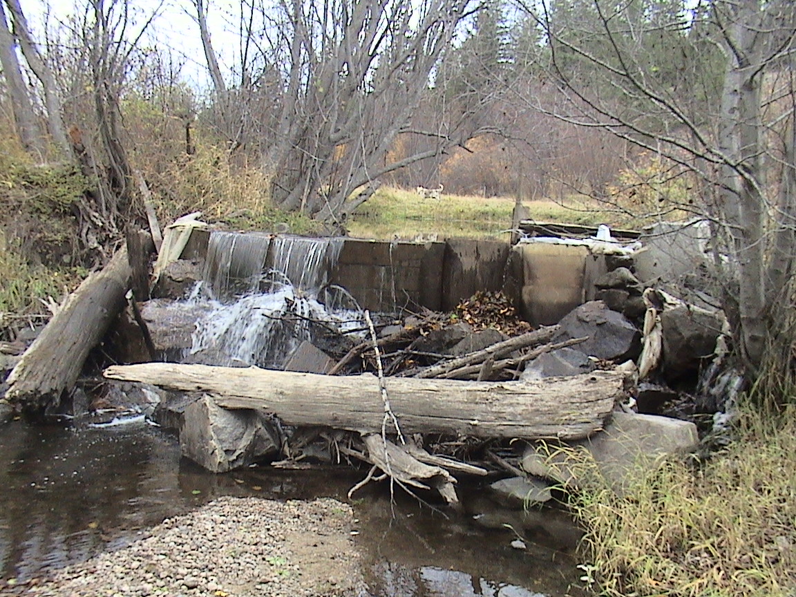
This creek is fed by June snow runoff and will then rise anywhere between 8 and 18" and will leave behind all kinds of remnants, as you can see in the picture.
In the middle of the dam are the three flood boards. On the far right is a plywood flood gate, to the right of it is the fish pool ladder and above it is the cat walk with the control plw.gate and screens. The dam is also a foot higher on the right to protect the turbine site in spring.
Image b
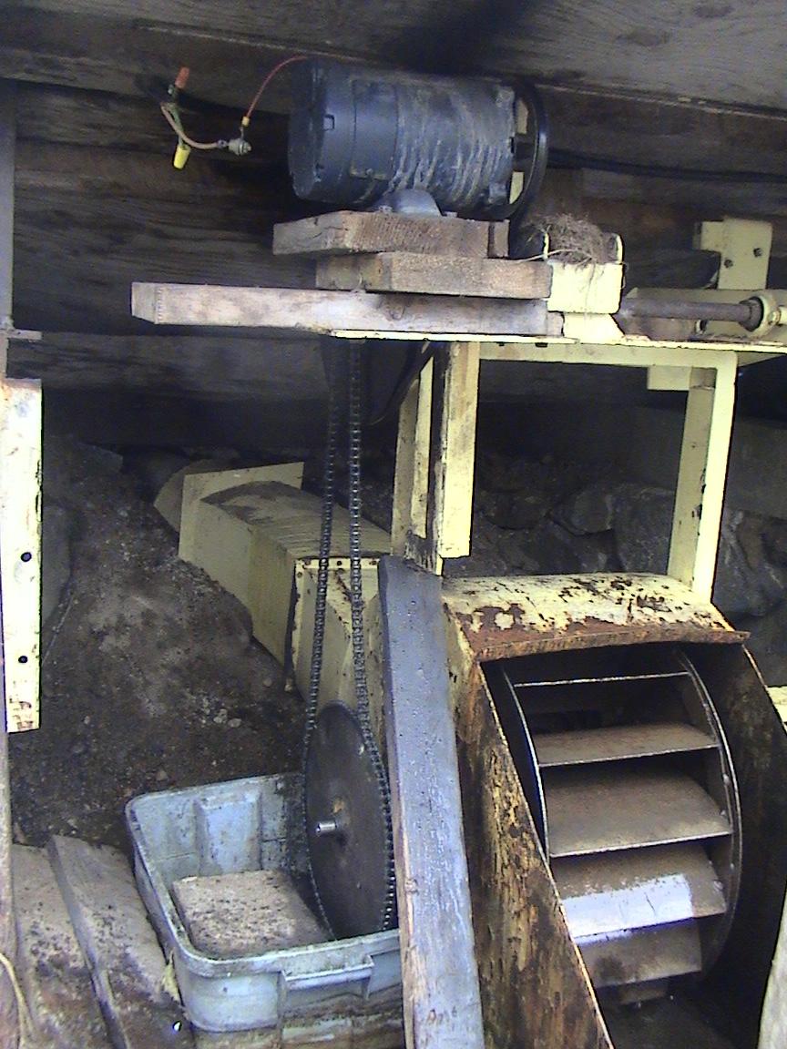
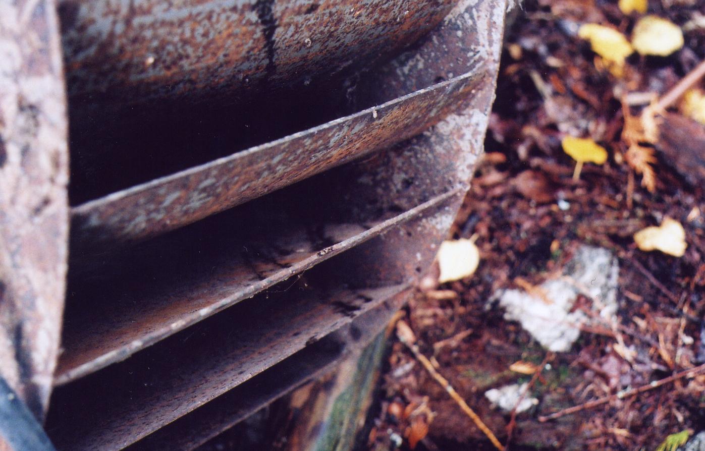
The temporary 2-1/2" side wall strip of the runner is well visible to which I tacked the Hydro blades into the different torque test positions at the beginning . So is the bent housing from unjamming the runner. Above is the LEESON NEMA FRAME PM 24V motor generator with the one way diode. The visible shaft on the top right is not in use. The drive is: Big to small sprocket, then big to medium (gen.) v-belt pulley. This turbine has been unthawed from a solid junk of ice a number of times over the years. How? Easy, we use a small propane screen heater under plastic which heats up the steel in a hurry. The thaw out time effort is pending on the amount of ice, anywhere from 1 to 5 hrs.
Image c
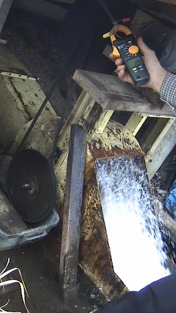
Here is Gerard showing you the 10.5A effort on November 3d 2007, which output will be now quite steady 'till spring. As you can see there isn't much left of the water velocity, the blades are free about half up. The spray is mainly from the speed of the runner which is not torqued down much, other wise you would see the water flowing out of the hydro blades; with less water flowing through it in summer for instance.
Image d
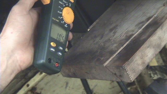
Image e

See the pile of dirt Bernice is standing on, it is the evidence of Gerard's hard labor unmucking the tailrace after last springs runoff!
Very level ground not much hydro head here; thus in early summer the water just rises it seams instead of running off!! Also sometimes the creek is all over the meadow instead of its bed. I had to lower the tailrace bed more then the creek bed by 15 inches to the length of about 40 feet to make use of the full 3' head. Doing this causes short term high water level in spring, which does not matter since the turbine is shut down on extreme volume runoff enyhow.
Some years ago I built this turbine below (Image 2 to 9) can be used for high and low pressure with a min. of a 6 foot head. Actually it can be used for three settings. For high pressure the smallest square of the inlet is used and the other one for medium pressure whereas the full width would be used for low pressure high volume. By the way I doubt my welding is good enough for a high pressure setting!! :) The runner measures at 12" DIA and 17-1/4 wide with the inlet at 10-1/2 by 16-1/2". The shaft of the runner is in two stubs. The blades are 2-3/4 or 70 mm wide 1/8th thick 4 out of a 4" or 100mm pipe cut with the band saw, use bi metal band saw blades and slow down the rpm for metal cutting. On mine I had to install another pulley and belt. Make certain never to cut into a torch burn (slag) of your working steel it will ruin the cutting blade instantly! This runner would be ideal for a 24" wide and 7-1/4 water depth 10"deep headrace (water channel) with a 10 foot head (drop) producing approx. 10 KW.
I farmed out the three 1/4" runner disks to someone who had a CNC laser cutter. If you have a very accurate plan with the blade grooves nicely laid out it makes it easier for them to produce an exact copy of the plan. Supply them with one of your curved blades for sizing the cuts. I made a full size blue print in those days; once I find it I'll add it to this page in picture form.
You will note the clearance between the side walls of the runner also the 60mm more narrow inlet to the width of the runner which is very important to enhance the life of the seals and bearings.
At the time I built the turbine I knew that I would not finish it, therefore I machined the stub shafts to size for assembling the runner into the housing. A key groove will have to be machined into the longer of the two stub shafts and the bearing and seal surfaces would have to be roughed down to 1/8" from the bearing and seal surfaces with centering holes. Then the stub shafts need to be welded into the 1/4" runner side walls, then rounding off nicely all leading edges of the 25 blades following by welding the blades into place and the final machining would follow with balancing as the next step.
Image1 8" high pressure Crossflow turbine
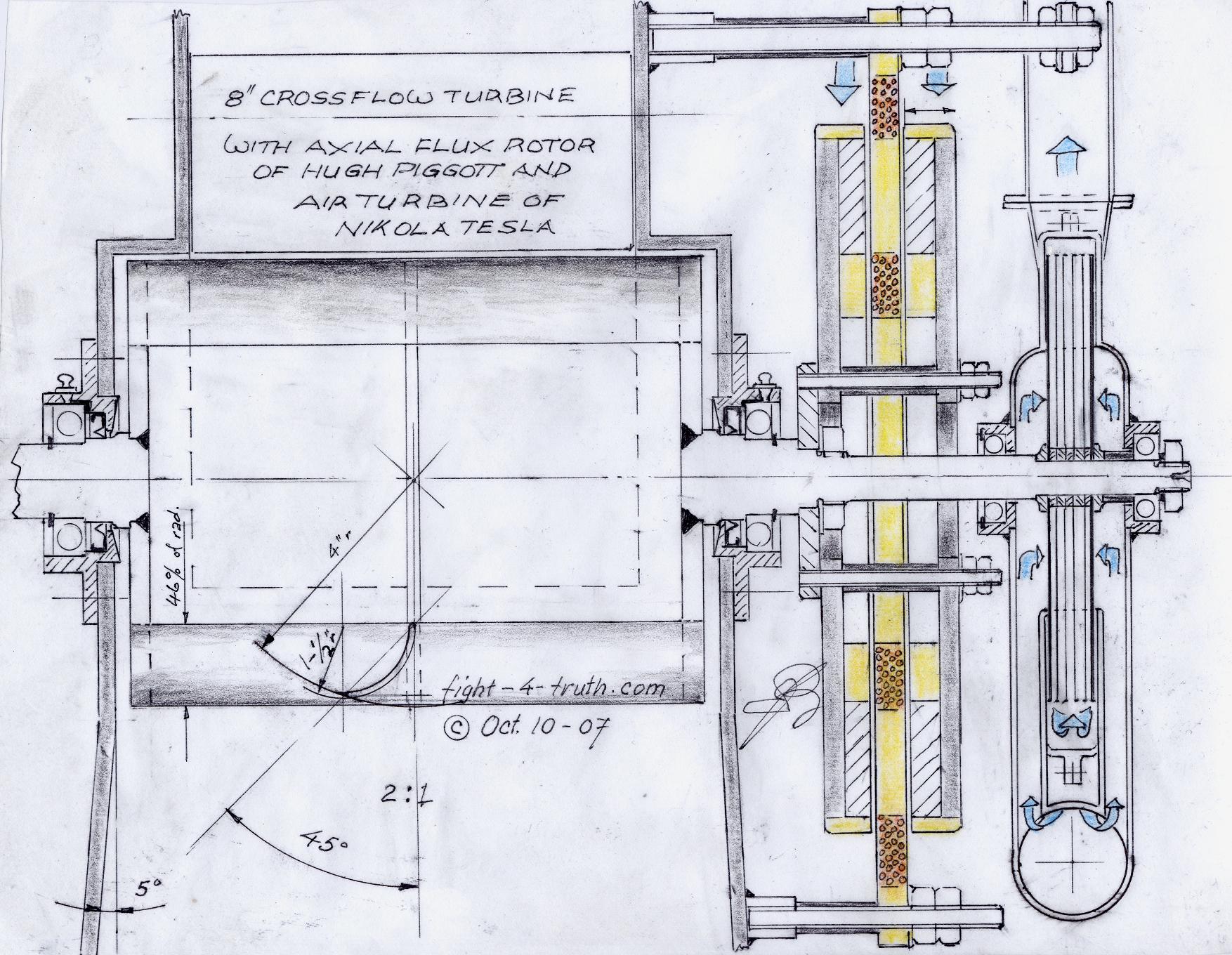
Image 2 Medium to high pressure crossflow turbine
Position for horizontal intake
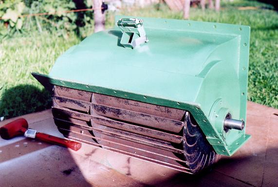
Image 3
Position for vertical intake
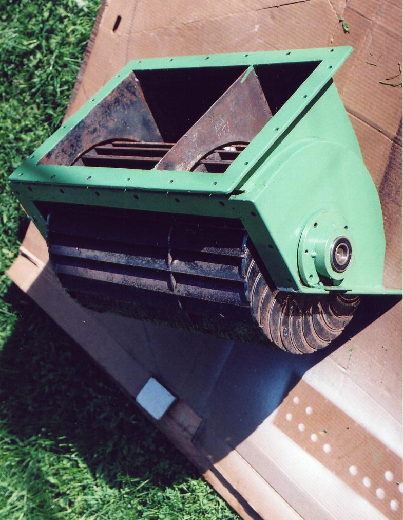
Image 4
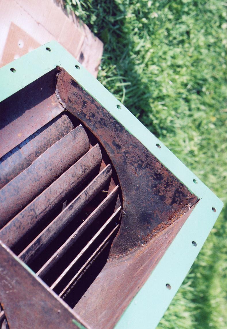
Image 5 High pressure crossflow runner`
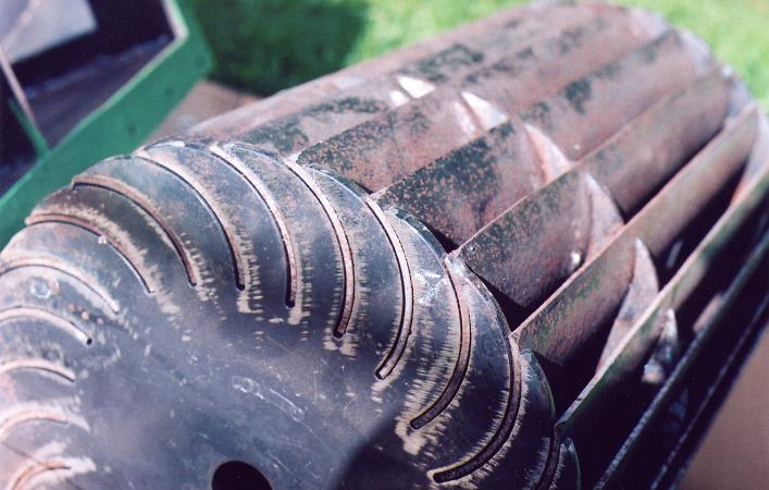
Image 6
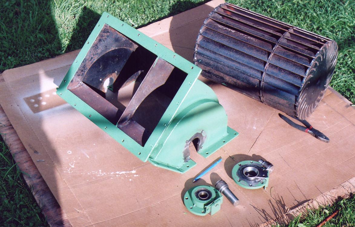
Image 7
A hole is drilled in each of the bearing flanches and threaded with 1/4 pipe tap to take a greace nipple. The dust cover of the bearing on the lip seal side is removed. For moisture removal off the lip seal note the slight taper on the inside of the flanch .
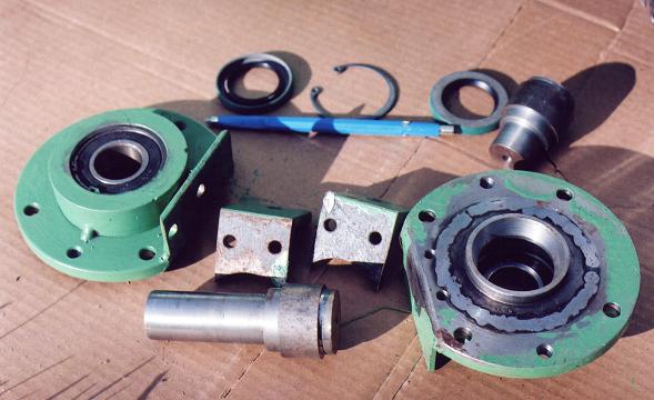
Image 8
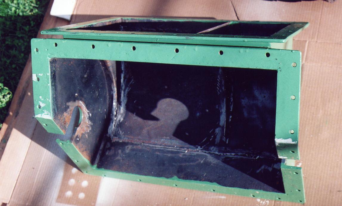
Image 9
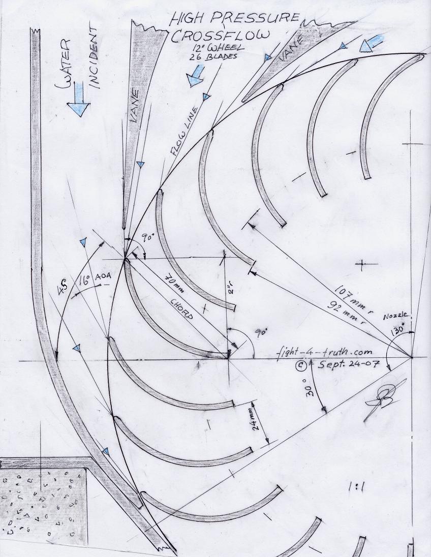
Image 10 Low pressure crossflow runner
This is a 1m /39-3/8" runner for a project some years back where much torque was needed, it never materialized .
Don't get your shirt in a not being overly hasty thinking to build this crossflow turbine. I have been reading quite a bit about the Tesla's water disc turbine, I have a feeling more power can be gained out of Tesla's simple turbine design, but here is another oppressed hydro system, of Viktor Schauberger's an Austrian, well worth looking at:
http://www.hasslberger.com/tecno/tecno_2.htm
K,C,R-factors
A friend told me that he is planning to build a house. Here is my Two Bits worth:
People build houses but have little knowledge of the importance of the C and R- factors in relation to building materials they use, never mind using the different factors to their advantage in designing their houses.
What suits you better, romance or practicality? Example:
I sat in some friends log home (huge logs) 'till late in a winters evening, the Air-tight stove blazing hot, the room temperature cozy at the beginning until about 4 hrs later when I got up because I was cold. Why, because he didn't place any fire wood into the stove, a possible reason would be beside the point... the thermal resistance value of a wood wall is only R-11(= only 11 resistance units).
K-Factor---> Thermal Conductivity Factor, the lower the K value the higher the insulating value...
C-Factor---> Thermal Conductance factor, the number of BTU's passing through a square foot of material...
R-Factor---> Thermal Resistance Factor, the higher the R value the better the insulating value...R=1/C...
A 2 by 6 insulated stud wall is approximately R-20 now, a staggered double 2 by 4 wall is around R-30 (R15x2). Now the trouble is, you have spent all this money and still have no room to store heat except the room you breath in which air has to be replaces with fresh oxygen, there goes your warm air out the window!! (unless you want an expensive air pump with filter system) Hence you have no heat reservoir.
Why do you have to have a heat reservoir? A heat reservoir is a labor, time and money saving.
More and more furnace hot water storage tanks are being installed for hot water boilers or in Europe called central radiant heat, which tanks are not needed if the home is built properly. Central radiant heat is definitely the most pleasant heat, surely no comparison to forced air with its dust blowers and drafts every where.
The magic words are Concrete with outside insulated Styrofam it is a combination that has been used in high-rises for years. The more concrete you use in your house the more heat storage you will have and the less it will cost you to heat it. Do not use the concrete/foam blocks on the market they totally defeat the purpose.
Concrete must be insulated from the outside via z-bars, Styrofoam, stucco mesh and stucco with an applied Acrylic finish. See Image a below
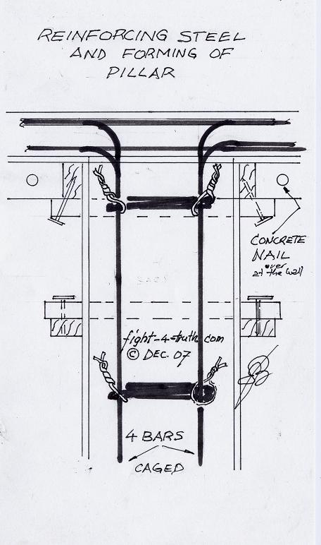
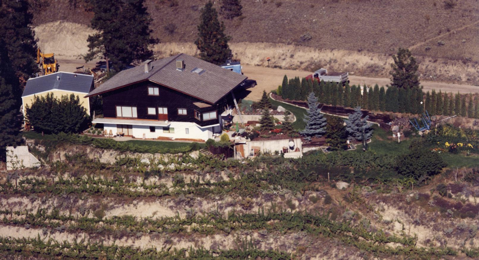
The house I build was the Swiss chalet stile with 4 foot eaves all around, see below. It had 3400 square feet floor space, full concrete basement with concrete stairs with lower wine cellar and greenhouse. The 5-1/2" concrete ceiling was supported length wise with a 5 x 60" concrete beam which was held up by two 12 x 12" posts/columns, there where also cantilevered balconies (with kitchen nook) insulated underneath with Styrofoam whereas the rest was a 2 by 6 structure with post and beam attic, which gave me two extra rooms with lot of storage space. It was a very warm house! see below
The hot water furnace consumed one single axle truck load of shavings with a little coal (20 Liter bucket/week) and little fire wood all winter. I heated the house once a day for 2 to 3 hrs and lost only 3º C within the 2x6 structure and 1.5º C within the concrete basement over night on January from one heating process to the next. I didn't mark down the 1.5º C at first, because I figured nobody would belief me anyway... well, fact is fact. It wasn't unusual to see my children running around bare feet on the warm concrete main floor through the winter months. Concrete absorbs the heat just like a stone will, while the furnace is on, then slowly releasing it until you fire up again.
Below is the wood fired hot water furnace of brother Fred and my design, which really works good and efficient, it resembles somewhat the locomotive boiler type. The efficiency in my home heating is best explained by: much heat, not much wood and no smoke for a very short period.
Fire-Watertube Combination Boiler with Swirl Combustion Posted: November 3d, 2008
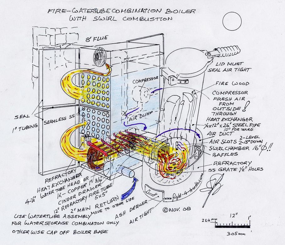
The air swirl in the combustion chamber caused by the air-slot arrangement adds to the air/fuel/smoke mixing, improving combustion and combustion temperature giving a rotary motion to the combustion gases in the fire chamber while forcing the hot gases in a circle "swirl" heating/consuming the fire wood from all sides in the chamber and burning most of the smoke within the swirl before being forced through the refractory fire tube, which is indeed the major cause for the high efficiency, high heat and 98% burning of the smoke, with the rest of the smoke and most small flying particles (fly ash) being burned in the 12" long refractory fire tube, thus the furnace operates smokeless, except on startup. Because of the smokeless very hot gases the firetubes in the boiler stay clean of soot and tar. It is therefore very essential for the two hot-gas-wings of the boiler be well insulated!!!
For a good heat transfer from the hot gases through the firetubes to the boiler water, the gases have to slow down through the firetubes, therefore the firetube area must be twice that of the refractory fire tube.
The furnace efficiency has a lot to do with the way the operator is loading the furnace, fuels used, the controlling of the air flow and pressure combined with the flue draft (back pressure), water feeds, pipe sizing and boiler operating temperatures. For maximum efficiency the boiler operating temperature should be kept at around 180º F or 90º C. Oversizing of the main heating circuit is always better since the flow can be slowed down and the operating temperature properly regulated, whereas if the piping is to small the boiler temperature will be hard to control and thus overheat, resulting with continuous emergency shut downs, without remedy. If you have a quick high heat producer, the boiler fluid must be moved quickly through the pipes and in big volume.
To prevent water-hammer and air locks in base board heat, all piping must have a steady climb with all high points an automatic air bleeder installed except the very top on a open circuit, which is open to the atmosphere. On 90º tee down-feeds for basement baseboard heat the special venturi-tee is used, forcing some of the hot water to move down due to the venturi effect and circulation pump pressure. Two and three floor buildings are ideal for automatic thermal circulation on power outages. I used 1" copper on my whole house circuit with the two upper floors being heated without the in line circulation pump!
The fire-watertube boiler produces very much heat, needs much overall circulating flow is used mainly for a baseboard / big reservoir water storage combination and is therefore not used for just base board heating. The watertube assembly is dismantled for the latter and the tube outlets caped off at the base of the boiler; a second circuit fluid return is plumbed also at the base of the boiler for the second scenario.
If you use the watertube setup, weld the 2" main return mounting/thread adapter onto the header on the opposite side of the 1" K-copper downcomer tube (which is a circulation enhancer and pressure equalizer between the boiler and watertube header).
The intake air must enter from the outside, is pressurized and preheated through the heat exchanger for the combustion chamber. The pressure is regulated via the furnace lid by a dump valve to the flue if pressure needs to be reduced. The combustion SS slots are cast into the refractory base at 90º from the center line tangent to the chamber wall with two in a downward direction of 15º and two level across alternately, with three of them protruding as baffles into the air stream of the channel on top of the refractory base.
The reason for the combustion chamber being 4" bigger then the feed pipe is the clearance around the fire wood at its base, which is assuring room for the air stream to pass by between the refractory walls and wood to keep the air swirl always in operation.
For the refractory base bottom end use a 3/16 steel plate with anchors welded to it and side mounts for the boiler connection, ash ss-grate and drawer tunnel. On top cast in 4bolts, which are the fasteners to later tighten down the feed tube/air channel assembly which sits on top of the 4 casted-in blower slot pipes (assure for good seal). The wooden plugs for the fire tube and swirl chamber casting design to be collapsible by pulling out the center of it. When preparing the refractory cement with water it will have to be a dry mix, make sure to use only enough water to bring it barely to the surface when vibrating. Practice on the flat slab which is placed on the back wall of the boiler base. Heed the curing time and firing up procedures.
For fuels, best is dry firewood and coal with bark mixed for minimum of fly-ash into the boiler side. Shavings or saw dust can be used if loaded combined with bark or fire wood intelligently. Obviously the base of the boiler side would therefore need cleaning more often (fine ash), which is easy and fast. If operated at proper temperatures, the boiler pipe tubing in this furnace design gets coated over time with only a thin layer of brown powder, which needs to be brushed out once a year. The whole furnace is insulated all around with at least 3" fiberglass batting or other means.
The refractory fire tube is recessed and sealed with stove rope one inch at the main base casting, whereas on the boiler side it enters about six inches underneath the boiler, pressed to an angle iron stop and held there with two tightening bars from the base of the feed pipe and base. The tube is also well insulated or a box is built with 1mm sheet metal and tacked holders holding the insulating batten to it with hinged doors or panel sliders wherever you need to get to the furnace for maintenance and also access for the main ash drawer.
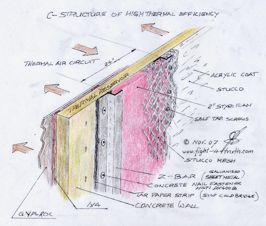
Image b
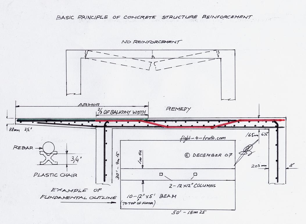
Image c
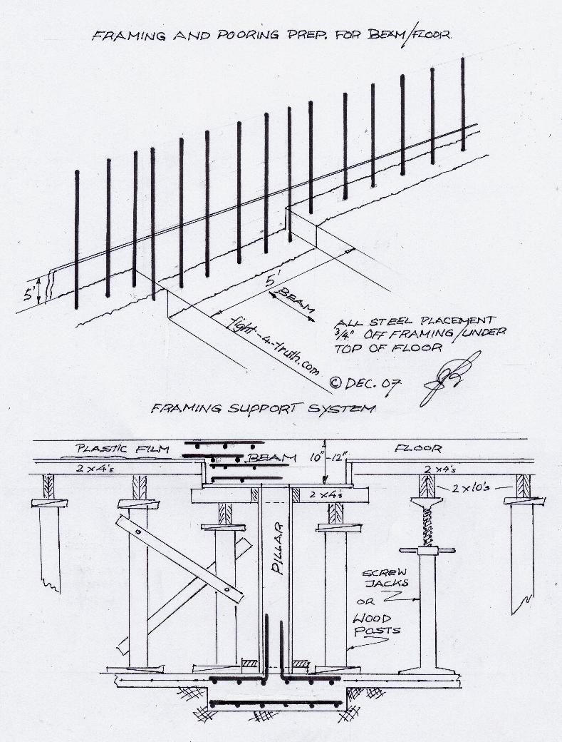
Image d
For my basement layout I used the space beneath the 5 foot beam for hallway and sprayed the ceiling; whereas in the other rooms I used carved and chestnut brown stained 2x4's hung from the concrete ceiling as channels for the 5/8"x4x4' white sprayed gyp-roc panels, instead of the T-bar system, to hide all the plumbing and copper. If you use 1/2" gyp-roc glue 1x4 wood-lath upright and diagonally across the top for strength.
Anybody who can afford to build a house can afford to build it with concrete according the principle the way I did. In order to save thousands of dollars and head aches, you would accomplish the cement forming yourself. I moved into the finished basement first with the main floor at insulated lockup stage. Besides having to give your plans to a high rise engineer for his stamp of approval no local yokel of a building inspector will have any say about your building procedure!! Just have your forming and re-bar work inspected by a high rise construction foreman who is approved by your engineer, before you poor it. Local engineers usually will not have enough knowledge and will therefore try to talk you out of building post and beam ceilings with cantilevered balconies. Some will also design concrete structures much to bulky and too expensive while hung up on old fashion engineering. The strength is in the size and placement of the reinforcing steel of the individual concrete structures not in the concrete volume, even though the concrete quality as in low slump factor No. for ceilings should be indicated by the engineer and the concrete supplier should be made aware that you will take samples and no water be added prior to poring but to use superplasticizers!!!
Use the electrical vibrator bar on every con.-poor you make and keep concrete wet for 7 days for full strength (keep soaking it down with a water hose). Don't use concrete sealers on surfaces used for heat storage.
Remember the conduits with the boxes in the walls and wood plugs at the ceiling to trill through for your electrical layout and plumbing.
Image f Image g
I used to jump up and down on the balcony enjoying the singing sound it made, just like a well
tuned guitar.
| INDEX
1. Crossflow turbines 2. Window Motor 3. Three foot head 4. High pressure runner 5. Nozzle design and guide vanes 6. Low pressure wheels 7. The ratio 8. Low pressure nozzle 9. Blade angles 10. Turbine blade layout 11. Runner size 12. Low pressure blade 13. Prony brake 14. Torque test 15. Turbine size 16. Draft tube 17. Load cotroll governor 18. Dam costruction 18a.Thread for micro hydro dam sites 19. 12 or 24V Inverter (alt. by Hugh Piggott) 20. The alternator |
20a. Crossflow Turbine Site 21. Turbine 6 foot head and up 22. 8" Crossflow turbine Tessla / Piggott 23. Image 2 CF1 24. Image 3 CF2 25. Image 4 CF3 26. Image 5 CF4 27. Image 6 CF5 28. Image 7 CF6 29. Image 8 CF7 30. Image 9 High pressure crossflow sketch 31. Image 10 Low pressure crossflow runner 32. Image 11 Low pressure crossflow sketch 33. Nikola Tesla turbines 35. 36. Fire-Watertube Boiler 37. Thermal structure 38. Concrete armored structure 39. Concrete forming |
Pass it on; it will be for the wellbeing of your own soul.
http://www.fight-4-truth.com/Alternative%20Energy%20Page.html
FOR THE WHOEVER-CONCERN
FOR ANY COURT-ORDER OR ANY OTHER AUTHORITY-VESSEL AGAINST THIS WEBSITE/OWNER IS WITH THE TRUTH-LANGUAGE-FORMAT-CLAIMS. FOR ALL COURTS-WORLD-WIDE ARE WITH THE ADJECTIVE/PRONOUN/ADVERB-MODIFICATION OF THE NOUN-LANGUAGE-FRAUD AND HAVE THEREFORE ZERO-JURISDICTION.