Page 2 of this
replicat. extension of Erwin's SG Work Shop
This is my 4" base
built up from the three coiler, called now SSG4. This 4 old coils are
each 6 filer 1 # 22 at 3ohm,5
#18AWG
for the five strands is 0.8 ohm at 150 ft, where 1 strand =
1.5
ohm.
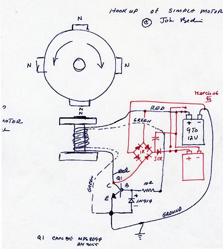
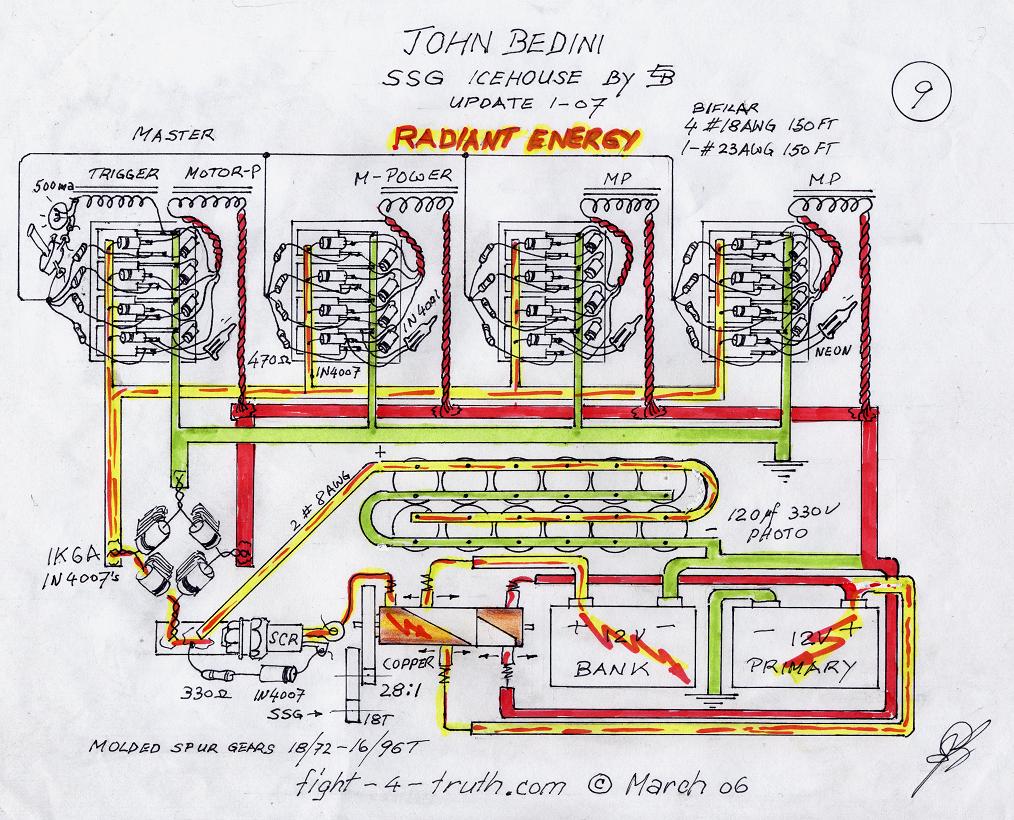
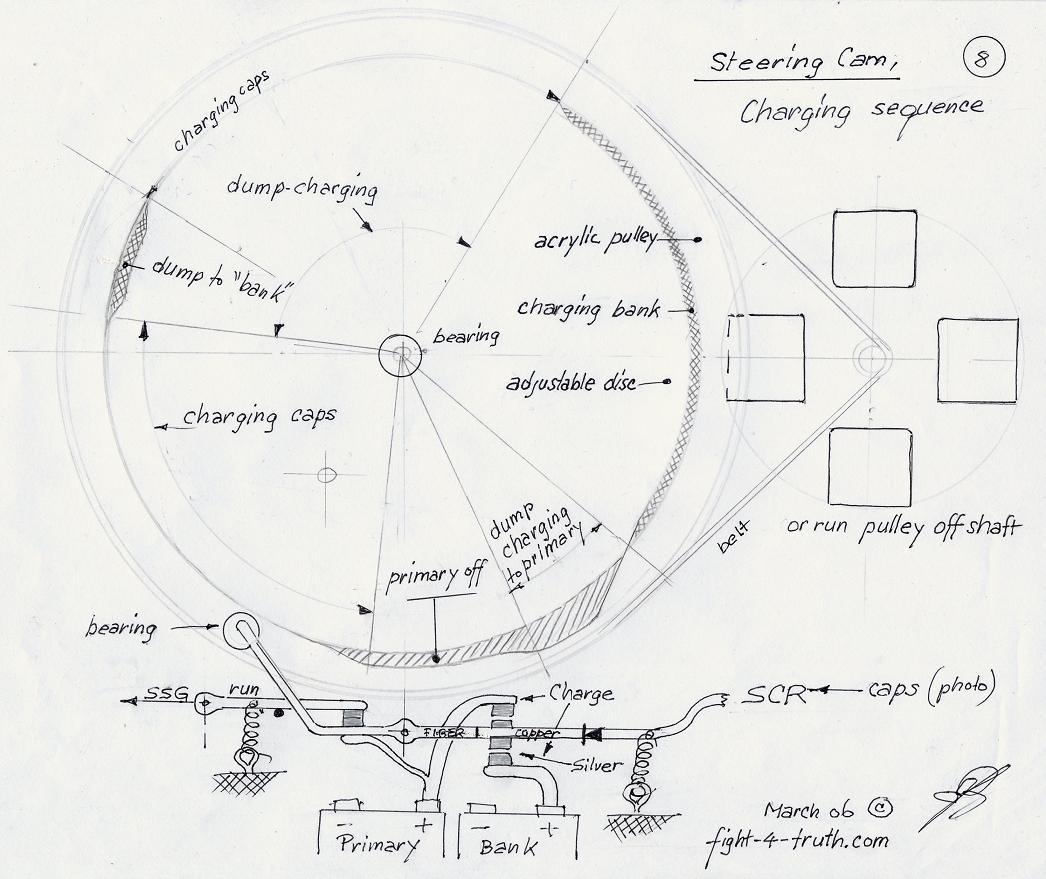
When I added the 12 photo caps 330V 100uF in parallel, the charging voltage was raised by 3.5V, measured across the SCR with the homemade 6 - 1K bridge. Then I took two 600V 8A FWBR's in series to reach that 1K volt line for comparison to my own bridge. The schematics for the setup are illustrated in the schematic page with the first one, I've used JB's drawing "hook up of simple motor" image1a, then SSG Icehouse by EB, take note of the ground, image11 and the Steering Cam with timing-discharge into the Battery bank and primary, Image12, the disk is quite big in its DIA for low RPM to get enough time for loading the caps more than once per revolution. If you use two or three disks stacked, the timing will be easier to adjust. I'm right in the middle of things, thought you might wonder over Easter (2006) what I'm up to, so here are a couple of drawings to look at... thought I might get you out of the chair with it, perhaps you'll beat me to the punch. :)
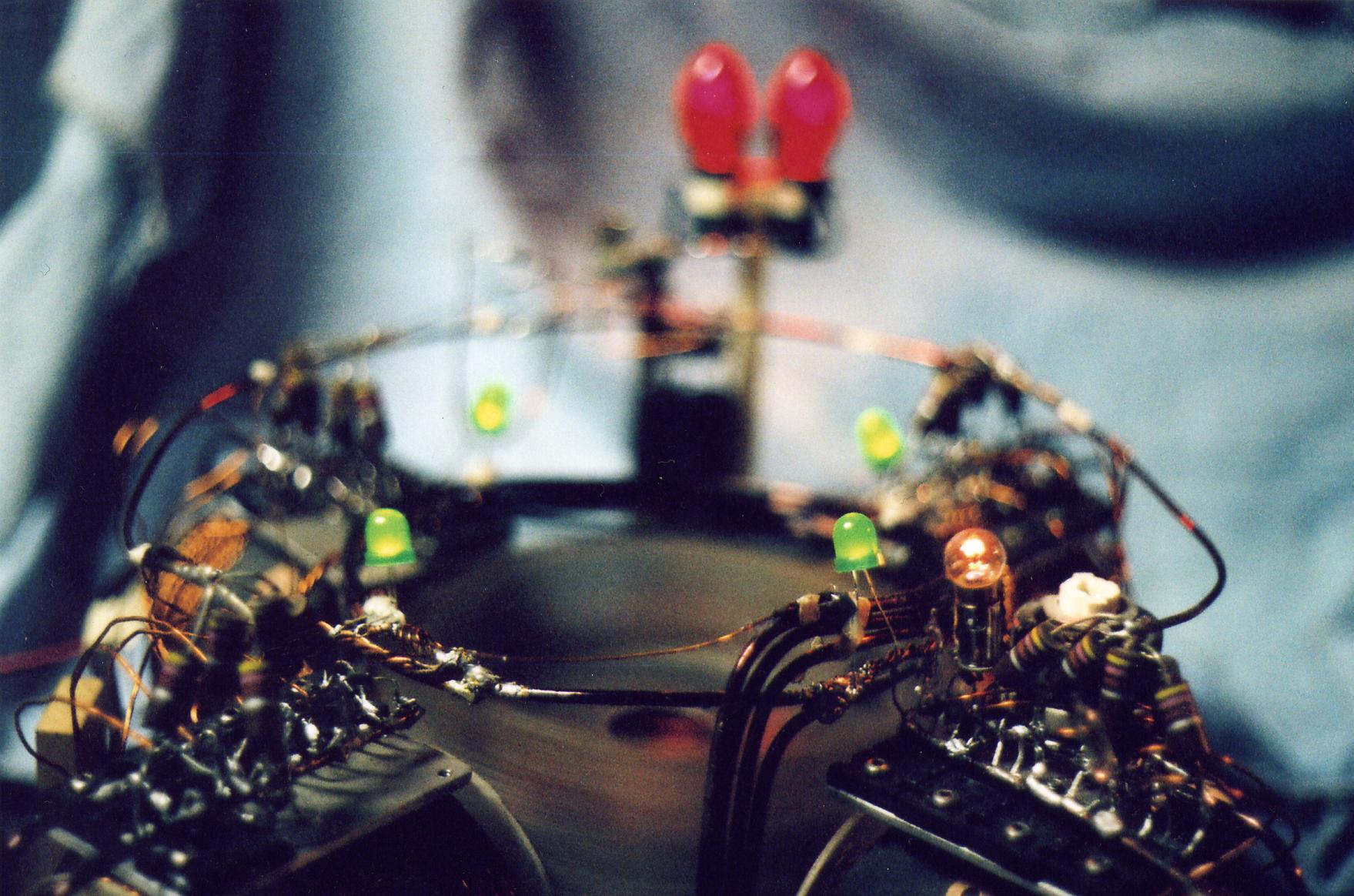
Below are a few pictures of my Icehouse replication for now. The purpose for the wrapping tape around the rotor is mainly for reducing wind.
Image 11,
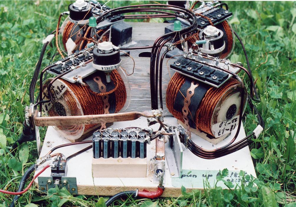
Image 12,
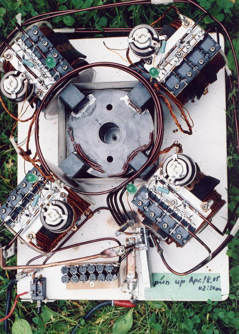
Image 13,
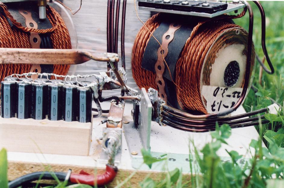
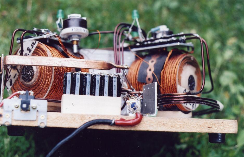
Image 14,
Now since we have Johns Bedini's schematic I changed things around a bit, by using one coil as the master and the other three as the slave coils. I removed the 5 strands off the heat sink and soldered them individually onto the 5 - MJL21194’s, 5 - 1N4007 on the collector-bus with one power strand in behind the diode on the collector terminal, 5 - 1N4001’s on the base and 5 - 470 Ohm resistors off of each base to the one Rheostat set at approx. 22 Ohm’s and lamp which has a 6.4 Ohm resistance (it was the only small 12 V bulb I had sitting around). Each strand on one transistor with the one bulb overall did in deed improve the voltage pressure in this case “It matters” although I have opposite results, depending on the circuit. Every improvement is a step in the right direction even if it is just more efficiency meaning that I could not detect any improvement in the charging end of it without cap pulsing. I tried it first without the bulb noticing the usual amperage steps from 2 to 6 amps settling back to 4.6, whereas with the lamp the current moved slowly from 1.5 to 2.7 A input and staying there with the small 12 V auto clearance lamp slightly glowing, meaning the use of the lamp caused a 1.9 current drop which we know by now. Using the right size lamp makes only sense if the setup is right and the proper symptoms are present, otherwise it just causes more current draw from the primary
The other three trigger wires of the slave coils I hooked up in series to a 1KV FWBR with a 330 V 120 uf cap with on – off switch powering a neon bulb at 75 V at first with this extra load making no difference to the machine on or off.
I guess what surprised me most with a 12 V input was the 19.8 Volts on the anode side of the SCR. The cathode side measures 12.6 V giving the machine a charging pressure input of a good 7 Volts over the battery voltage which is good for cap pulsing. It climbed up to 7.5V when I replace the FWBR for a voltage doubler reaching around 109 V . This 7.5 V was the highest pressure over the battery voltage I have reached so far. To protect the 5W bulbs I soldered a 100Ohm 2W resister in front of two 5W 110 V Christmas bulbs which made the intake current dropt 2.7 by 0.2 A with a steady charging current of 0.3 A. The 100 Ohm value I found by adjusting the glow of the bulb with a rheostat. Actually for a test only, I hooked a string of 24 Christmas bulbs to it and made the SSG really snort by slowing down some in RPM and pulling 4 Amps. They where all lit up to a nice glow! This was only one thin 23AWG wire (trigger wires) off three coils in series !!!
The charging current battery input was between 0.3 and 0.5 amps which I think is acceptable.
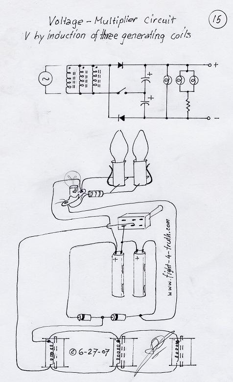
Voltage-Doubler Rectifier, see Image 15 below (I am not sure whether it is technically correct, but I think you'll get the picture). First and second diode forward biased during their positive and negative half cycle. Polarized coil lead ---->forward biased 1N007 with 2 - 330V 120uf photo caps in series with south-pole coil lead in between, another diode forward biased back to P coil lead from the second negative cap. Bulb is connected with 100Ohm 2W resistor off first pos. cap and sec. negative cap, running at 83V my rotor slightly out of balance with the glowing filaments vibrating (which is the reason for the resistor) looking like a grasshopper ready for the jump! :)
Running the SSG at a 13.6 VDC input drawing 2.2 amps at 37.5 VAC out of the three coils being connected in series using the #22 AWG left over trigger wires hooked to the Voltage-Doubler Rectifier with 120VDC out running the two Christmas lights. The machine's charging wires where unhooked, operating it as a motor-generator. I also unscrewed the two bulbs and connected a standard 110V 50W light bulb to the outlet instead, but not after having increased the intake to 15VDC drawing 4amps with an output of 137VDC lighting it up steady to about 80%. I assume with heavier wires, meaning less resistance, I would have had better performance. The next step is two drivers at 30º leading out of phase in relation to the next of the six independent generating coils, with a back popper off of the drivers. See:
http://www.sayedsaad.com/fundmental/index.htm on the 5th page: "Voltage waves 180° out of phase".similar to Image 16a in my Schematics Illustrated page.
Image 15
For some reason one cannot see the lit up red filaments very good in this pictures.
Image 16
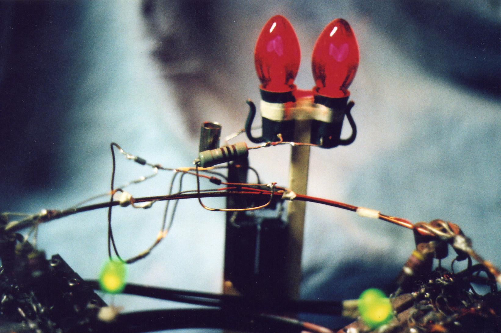
Image 17
<------Replication 1
When I added the 12 photo caps 330V 100uF in parallel, the charging voltage was raised by 3.5V, measured across the SCR with the homemade 6 - 1K bridge. Then I took two 600V 8A FWBR's in series to reach that 1K volt line for comparison to my own bridge. The schematics for the setup are illustrated in the schematic page with the first one, I've used JB's drawing "hook up of simple motor" image1a, then SSG Icehouse by EB, take note of the ground, image11 and the Steering Cam with timing-discharge into the Battery bank and primary, Image12, the disk is quite big in its DIA for low RPM to get enough time for loading the caps more than once per revolution. If you use two or three disks stacked, the timing will be easier to adjust. I'm right in the middle of things, thought you might wonder over Easter (2006) what I'm up to, so here are a couple of drawings to look at... thought I might get you out of the chair with it, perhaps you'll beat me to the punch. :)
Below are a few pictures of my Icehouse replication for now. The purpose for the wrapping tape around the rotor is mainly for reducing wind.
Image 11,
Image 12,
Image 13,
Image 14,
110V
Christmas bulbs glowing
Now since we have Johns Bedini's schematic I changed things around a bit, by using one coil as the master and the other three as the slave coils. I removed the 5 strands off the heat sink and soldered them individually onto the 5 - MJL21194’s, 5 - 1N4007 on the collector-bus with one power strand in behind the diode on the collector terminal, 5 - 1N4001’s on the base and 5 - 470 Ohm resistors off of each base to the one Rheostat set at approx. 22 Ohm’s and lamp which has a 6.4 Ohm resistance (it was the only small 12 V bulb I had sitting around). Each strand on one transistor with the one bulb overall did in deed improve the voltage pressure in this case “It matters” although I have opposite results, depending on the circuit. Every improvement is a step in the right direction even if it is just more efficiency meaning that I could not detect any improvement in the charging end of it without cap pulsing. I tried it first without the bulb noticing the usual amperage steps from 2 to 6 amps settling back to 4.6, whereas with the lamp the current moved slowly from 1.5 to 2.7 A input and staying there with the small 12 V auto clearance lamp slightly glowing, meaning the use of the lamp caused a 1.9 current drop which we know by now. Using the right size lamp makes only sense if the setup is right and the proper symptoms are present, otherwise it just causes more current draw from the primary
The other three trigger wires of the slave coils I hooked up in series to a 1KV FWBR with a 330 V 120 uf cap with on – off switch powering a neon bulb at 75 V at first with this extra load making no difference to the machine on or off.
I guess what surprised me most with a 12 V input was the 19.8 Volts on the anode side of the SCR. The cathode side measures 12.6 V giving the machine a charging pressure input of a good 7 Volts over the battery voltage which is good for cap pulsing. It climbed up to 7.5V when I replace the FWBR for a voltage doubler reaching around 109 V . This 7.5 V was the highest pressure over the battery voltage I have reached so far. To protect the 5W bulbs I soldered a 100Ohm 2W resister in front of two 5W 110 V Christmas bulbs which made the intake current dropt 2.7 by 0.2 A with a steady charging current of 0.3 A. The 100 Ohm value I found by adjusting the glow of the bulb with a rheostat. Actually for a test only, I hooked a string of 24 Christmas bulbs to it and made the SSG really snort by slowing down some in RPM and pulling 4 Amps. They where all lit up to a nice glow! This was only one thin 23AWG wire (trigger wires) off three coils in series !!!
The charging current battery input was between 0.3 and 0.5 amps which I think is acceptable.
Voltage-Doubler Rectifier, see Image 15 below (I am not sure whether it is technically correct, but I think you'll get the picture). First and second diode forward biased during their positive and negative half cycle. Polarized coil lead ---->forward biased 1N007 with 2 - 330V 120uf photo caps in series with south-pole coil lead in between, another diode forward biased back to P coil lead from the second negative cap. Bulb is connected with 100Ohm 2W resistor off first pos. cap and sec. negative cap, running at 83V my rotor slightly out of balance with the glowing filaments vibrating (which is the reason for the resistor) looking like a grasshopper ready for the jump! :)
Running the SSG at a 13.6 VDC input drawing 2.2 amps at 37.5 VAC out of the three coils being connected in series using the #22 AWG left over trigger wires hooked to the Voltage-Doubler Rectifier with 120VDC out running the two Christmas lights. The machine's charging wires where unhooked, operating it as a motor-generator. I also unscrewed the two bulbs and connected a standard 110V 50W light bulb to the outlet instead, but not after having increased the intake to 15VDC drawing 4amps with an output of 137VDC lighting it up steady to about 80%. I assume with heavier wires, meaning less resistance, I would have had better performance. The next step is two drivers at 30º leading out of phase in relation to the next of the six independent generating coils, with a back popper off of the drivers. See:
http://www.sayedsaad.com/fundmental/index.htm on the 5th page: "Voltage waves 180° out of phase".similar to Image 16a in my Schematics Illustrated page.
Image 15
For some reason one cannot see the lit up red filaments very good in this pictures
Image 16
Image 17
Capacitor
discharge via SCR
Roamer, a sharp radiant fan, sugested to use simply a cheap rubber wheel with cam and contact brass strips driven directly off the SG shaft. He also mentioned in replacement of the above to use a 6V zener 1 watt diode with a 100 Ω resistor in between the positive 1000uF 330V photo cap and the 25A 800V SCR gate.
I played around with the setup some, getting the zener with a 500Ω resister to dump the caps at 26 and 30V. Then I tried it with a resistance of 2.2KΩ, well...not only was it dumping my 1200uF bank (above) between 60 and 70V through the SCR but the RPM of the SSG was in tune snorting with the cycle and so was the resitance lamp flashing while the volt needle showed every dump very dramatically whereas the amp meter indicated from 0.600 to 1.5A charging rate. It was a nice little exercise but of corse no good. By the way I had used the battery cover.
With the 100Ω resister it worked the best between 23 and 24V and between a 300 and 600mA with a steady charging rate of 8 sec. per 100V digit hooked to two 1000 amp batteries.
If you are not quite sure what I am writing about, then look at Image 12 where you you'll see in between the cap bank and the SCR a IN4008 diode soldered to the copper bar connected to a 330Ω resistor onto the SCR gate. Replace the IN4008 with a 6V 1 watt zener diode pointing the silver ribbon of the zener towards the copper bar and replace the 330 with a 100Ω resister.
<------Replication 1
Pass it on; it will be for the wellbeing of your own soul.
http://www.fight-4-truth.com/Replication 2.html
:
COPY-RIGHT/COPY-CLAIM : DECEMBER ~19, 2005 BY
THE Erwin-Badertscher, OWNER OF THE ERWIN BADERTSCHER(SIC), TRADE-NAME.